Undersea pipe including an internal liner

a technology of internal liner and underwater pipe, which is applied in the direction of mechanical equipment, manufacturing tools, and so on, can solve the problems of high cost, difficult control of process, and considerable complexity of work, and achieve the effect of less expensive implementation

Active Publication Date: 2010-05-25
SAIPEM SA
View PDF21 Cites 21 Cited by
  • Summary
  • Abstract
  • Description
  • Claims
  • Application Information

AI Technical Summary

Benefits of technology

[0014]The object of the present invention is to provide methods and devices for lining undersea pipes, and methods and devices for welding together pipe elements as lined in this way, which methods and devices should be simultaneously mechanically reliable, simpler and less expensive to implement, particularly when assembly is performed on site on board a ship at sea, with pipe elements of short length suitable for being laid from a ship at sea.
[0026]It will be understood that bonding the terminal portion of the liner by adhesive avoids any need to implement a locking ferrule or other screwing or crimping with a collar, and the bonding of the junction sleeve likewise does not require any implementation of a locking ferrule or screwing or some other crimping tool that deforms said sleeve, with this applying both during initial fabrication of the pipe element and when assembling together two pipe elements.
[0028]After two pipe elements have been joined together, the outside surface of the central portion of the sleeve and the corresponding inside surface of the steel wall of the non-lined terminal portion of said pipe element co-operate to define an annular chamber because of their different diameters respectively on the outside and the inside. This makes it possible to avoid any direct contact between the stainless steel or Inconel alloy of the sleeve and the steel of the pipe element. In the event of water penetrating into said chamber when the pipe is a water injection pipe, such direct contact could lead to electrochemical phenomena of corrosion of the steel pipe, insofar as said mechanical connection between the sleeve and the liner is not necessarily leaktight. The lack of contact between the sleeve and the steel wall of the pipe allows conventional welding to be performed of the type that is commonly used for welding pipe lines, and it makes it possible to avoid the use of expensive welding using a noble alloy identical to that which might be used as the material constituting said sleeve, in particular an Inconel alloy.
[0041]According to another advantageous characteristic of the present invention, cold plasma treatment is performed using a device situated outside said pipe element on the zones of the outside surfaces of the thermoplastic liner pipe that are to be coated in adhesive or that are to be pressed against an adhesive-coated zone of the steel wall of a said pipe element, in order to encourage bonding effectiveness.
[0045]Preferably, prior to step 1), said thermoplastic liner pipe is heated so as to make it easier to stretch it to a smaller diameter, preferably by passing through a die.

Problems solved by technology

The problem which then arises is how to provide protection against corrosion for the non-lined zone extending between the end of the liner in pipe N and the end of the liner in the following pipe N+1.
However, that cost becomes unacceptable when the unit length of each pipe element is 24 m or 48 m. In addition, the welding of the connection must be performed over the entire thickness of the pipe using the same noble metal, in general Inconel, thereby considerably complicating the work and leading to a cost that is very high, since the unit rate at which metal is deposited is much smaller and the process is more difficult to control than conventional welding on ordinary steel.
Finally, it is very difficult to perform quality control on the welding, and for certain types of anti-corrosion material, it is practically impossible to perform such welding in a manner that is reliable and repeatable, in limited time.
This runs the risk of damage during welding if welding is not performed using the same alloy, and of corrosion in the event of water infiltrating between the liner and the outer steel pipe.
In addition, the re-bored zone of each steel outer pipe presents a connection zone of thickness that is smaller than the thickness of the main portion of the pipe, thereby creating a zone of weakness.
In GB-2 391 597 and WO-2004 / 015321, a tool for crimping by expanding the tubular junction sleeve or other connection elements needs to be positioned and operated from the free end of the pipe, i.e. from a distance of 24 m to 48 m, when laying such pipes at sea from a J-lay tower, which can present considerable technical difficulty from an operational point of view and from a quality control point of view.
That represents a major risk of corrosion when using a tubular sleeve of a corrosion-resistant alloy of the Inconel type and when in the presence of water at the interfaces between the tubular sleeve, the liners, and the steel walls of the pipe elements.
That type of structure for lining and assembling two pipe elements for assembly, as described in WO-2004 / 011840, with permanent perforations through the tubular junction sleeve, which may in part come directly into contact with the steel wall of the pipe, is thus not suitable for making water injection pipes, and in particular pipes for injecting sea water, particularly if the sea water has not been passivated.

Method used


Image

  • Undersea pipe including an internal liner
  • Undersea pipe including an internal liner
  • Undersea pipe including an internal liner

Examples


Embodiment Construction

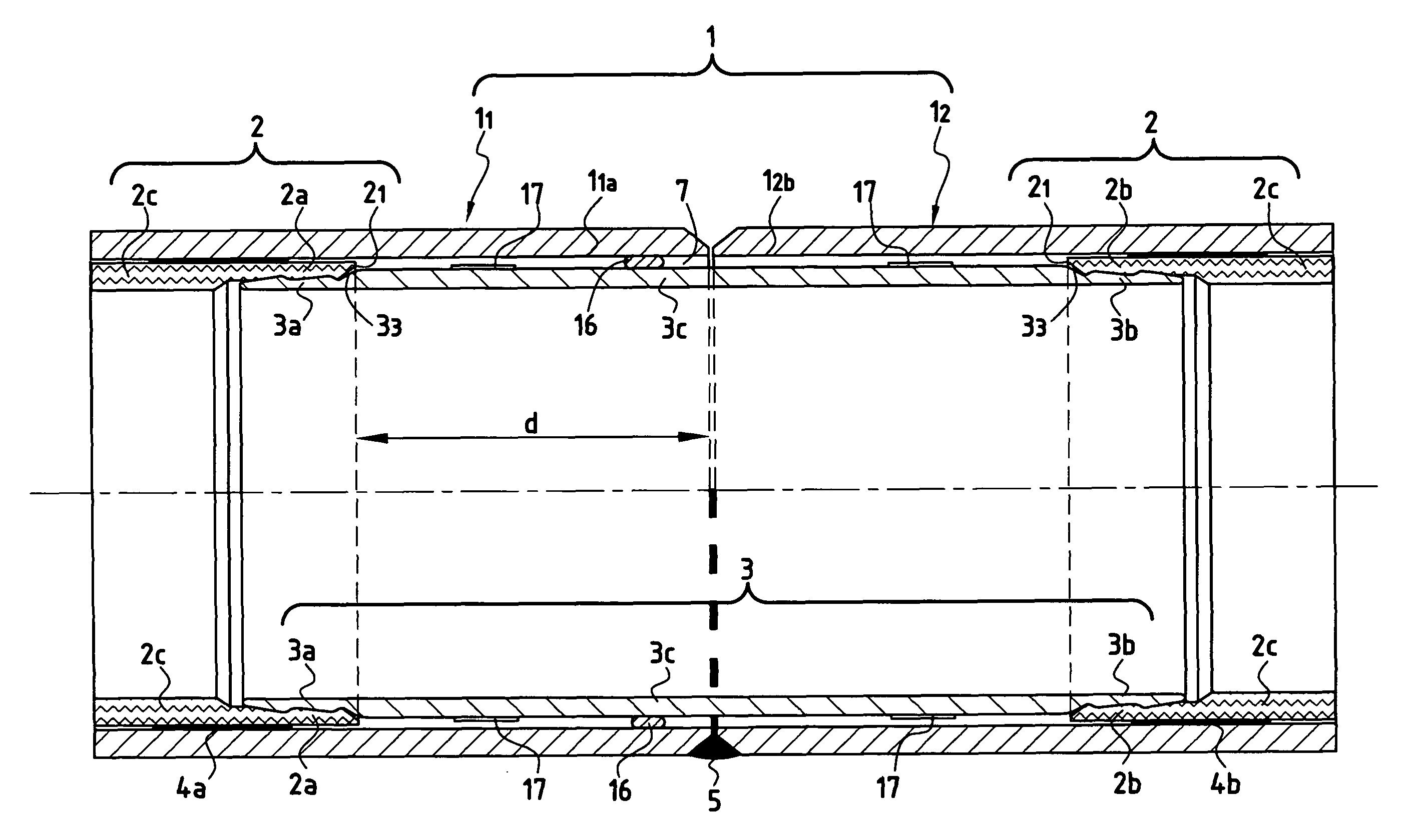
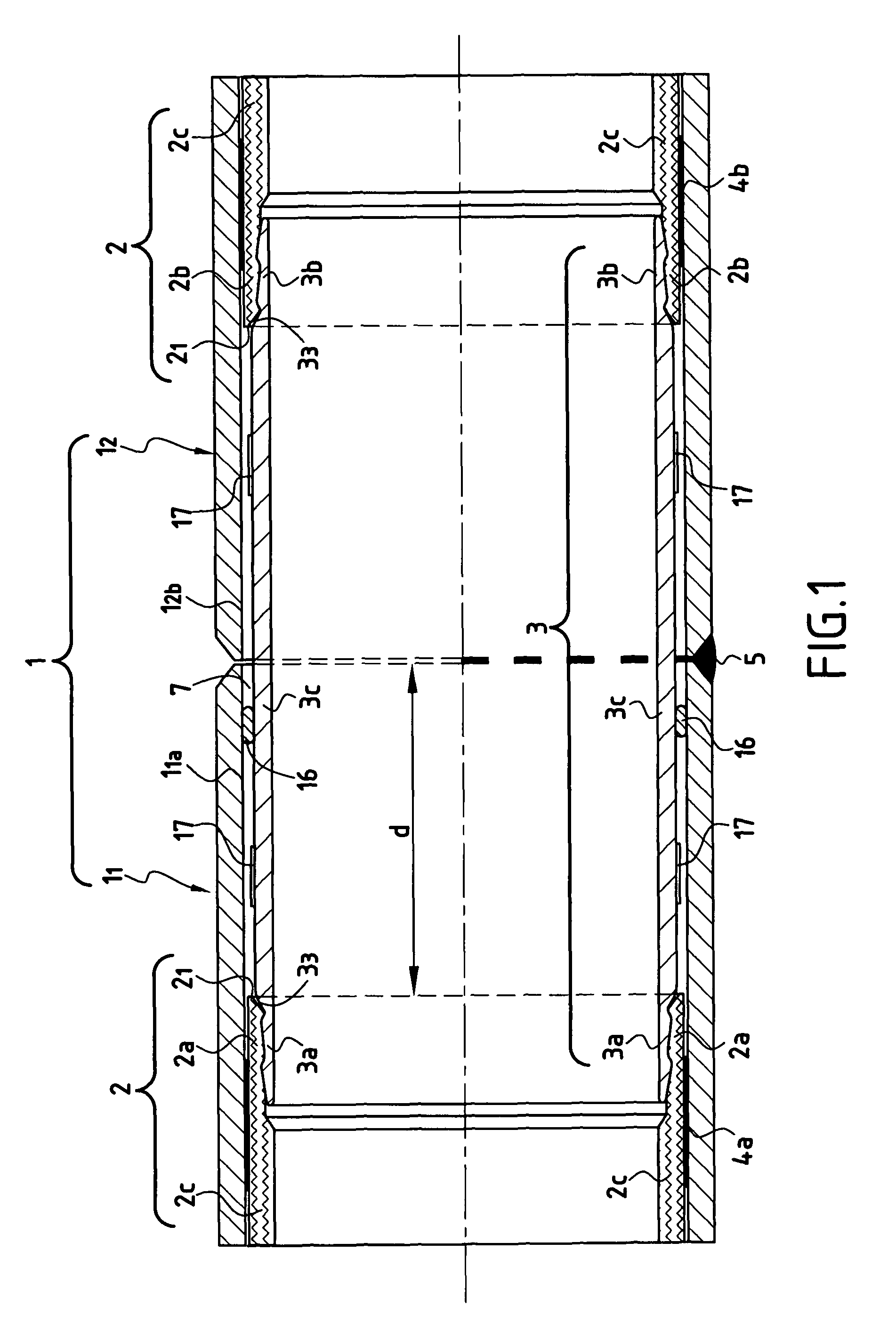
[0066]FIG. 1 shows a pipe of the invention comprising at least two pipe elements 11, 12 with internal liners that are assembled end to end, in which the ends of the two pipe elements are welded to each other at 5, and in which each pipe element comprises:[0067]an inner liner of thermoplastic material 2 presenting at each end a terminal portion 2a, 2b of thickness that is reduced relative to the thickness of the main portion 2c of said liner, defining a surface of revolution of inside diameter that is greater than that of the main portion 2c of said liner and terminating at a certain distance d from the end of said pipe element, having an axis XX′ that coincides substantially with the axis of the pipe elements 11, 12. The outside surface of each said terminal portion 2a, 2b of the inner liner is locked by adhesive bonding 4a, 4b between the end of the liner at or close to said terminal portion 2a, 2b of reduced thickness of the liner and the corresponding inside surface of the steel ...


PUM

PropertyMeasurementUnit
lengthaaaaaaaaaa
lengthaaaaaaaaaa
lengthsaaaaaaaaaa

Abstract

A pipe (1) comprising at least two pipe elements (11, 12) having internal liners of plastic material (2), the pipe elements being assembled end to end, in which the ends of the two pipe elements are welded (5) together and in which the ends of the internal liners (2) of plastic material of each of the pipe elements are joined together by a tubular junction sleeve (3) of material that withstands corrosion and that co-operate with the ends (2a, 2b) of the liners by mutual engagement via a notched surface (32), said liner ends (2) presenting reduced thickness (2a, 2b) and being bonded against the steel wall of said pipe by adhesive (4a, 4b).

Description

PRIORITY CLAIM[0001]This is a U.S. national stage of application No. PCT / FR2005 / 002395, filed on Sep. 28, 2005. Priority is claimed on the following application(s): Country: France, Application No.: 04 / 11055, Filed: Oct. 19, 2004, the content of which are incorporated here by reference.THE FIELD OF THE INVENTION[0002]The present invention relates to the field of undersea pipes that convey corrosive fluids, in particular sea water, and that include internal liners fitted therein by being threaded therethrough, said liners withstanding said corrosion.[0003]The invention relates more particularly to connecting together two unit pipe elements having internal liners, and more particularly still, it relates to connecting together elements that are 24 meters (m) or 48 m long and that are to be installed in oil fields in deep water, e.g. 2000 m to 3000 m deep, or even more, from a laying ship that is fitted with J-lay towers.BACKGROUND OF THE INVENTION[0004]The rehabilitation of water, gas,...

Claims


Application Information

Patent Timeline
Patent Type & Authority Patents(United States)
IPC IPC(8): F16L9/14
CPCF16L1/19F16L58/1036F16L13/0263
Inventor PIONETTI, FRANCOIS-REGIS
Owner SAIPEM SA
Why Eureka
Try Eureka