Bidirectional buck boost DC-DC converter, railway coach drive control system, and railway feeder system

a buck boost and converter technology, applied in the direction of process and machine control, pulse technique, instruments, etc., can solve the problem that the buck boost dc-dc converter as described above cannot control curren

Inactive Publication Date: 2010-05-25
MITSUBISHI ELECTRIC CORP
View PDF10 Cites 143 Cited by
  • Summary
  • Abstract
  • Description
  • Claims
  • Application Information

AI Technical Summary

Benefits of technology

[0014]According to an aspect of the present invention, there is provided a bidirectional buck boost DC-DC converter in which a direct-current power is supplied bidirectionally between two direct-current voltage sources of a primary-side power supply and a secondary-side power supply. The bidirectional buck boost DC-DC converter includes a primary-side converting unit that is connected to an input / output terminal of the primary-side power supply and performs a power conversion operation on the primary-side power supply; a secondary-side converting unit that is connected to an input / output terminal of the secondary-side power supply and performs a power conversion operation on the secondary-side power supply; a coupling unit that connects the primary-side converting unit and the secondary-side converting unit to each other and that mediates supply and reception of a power between the primary-side converting unit and the secondary-side converting unit; and a control unit that detects at least a voltage of the primary-side converting unit on a power supply side and a voltage of the secondary-side converting unit on a power supply side from among the voltage of the primary-side converting unit on a power supply side, the voltage of the secondary-side converting unit on a power supply side, and a voltage at an arbitrary point between a positive-electrode-side connecting terminal and a negative-electrode-side connecting terminal of the coupling unit each connecting the primary-side converting unit and the secondary-side converting unit, detects at least one of a current flowing into / out of the primary-side converting unit, a current flowing into / out of the secondary-side converting unit, and a current flowing into / out of the coupling unit, controls so that a selected one of detected currents is consistent with a command value corresponding to the selected one of the detected currents, and that controls a power conversion operation on the primary-side converting unit and the secondary-side converting unit based on detected voltage of the primary-side converting unit on a power supply side, detected voltage of the secondary-side converting unit on a power supply side, the selected one of the currents, and a signal based on the command value corresponding to the selected one of the currents, so that a direction and a magnitude of a power flowing bidirectionally between the primary-side power supply and the secondary-side power supply can be controlled to be continuously variable on instantaneous value basis regardless of a magnitude relation between a voltage of the primary-side power supply and a voltage of the secondary-side power supply in a state where the two direct-current voltage sources are connected to each other.

Problems solved by technology

However, the bidirectional buck boost DC-DC converter as described above cannot control current when a primary-side voltage is lower than a secondary-side voltage in the converter because of the circuit configuration.

Method used


Image

  • Bidirectional buck boost DC-DC converter, railway coach drive control system, and railway feeder system
  • Bidirectional buck boost DC-DC converter, railway coach drive control system, and railway feeder system
  • Bidirectional buck boost DC-DC converter, railway coach drive control system, and railway feeder system

Examples


first embodiment

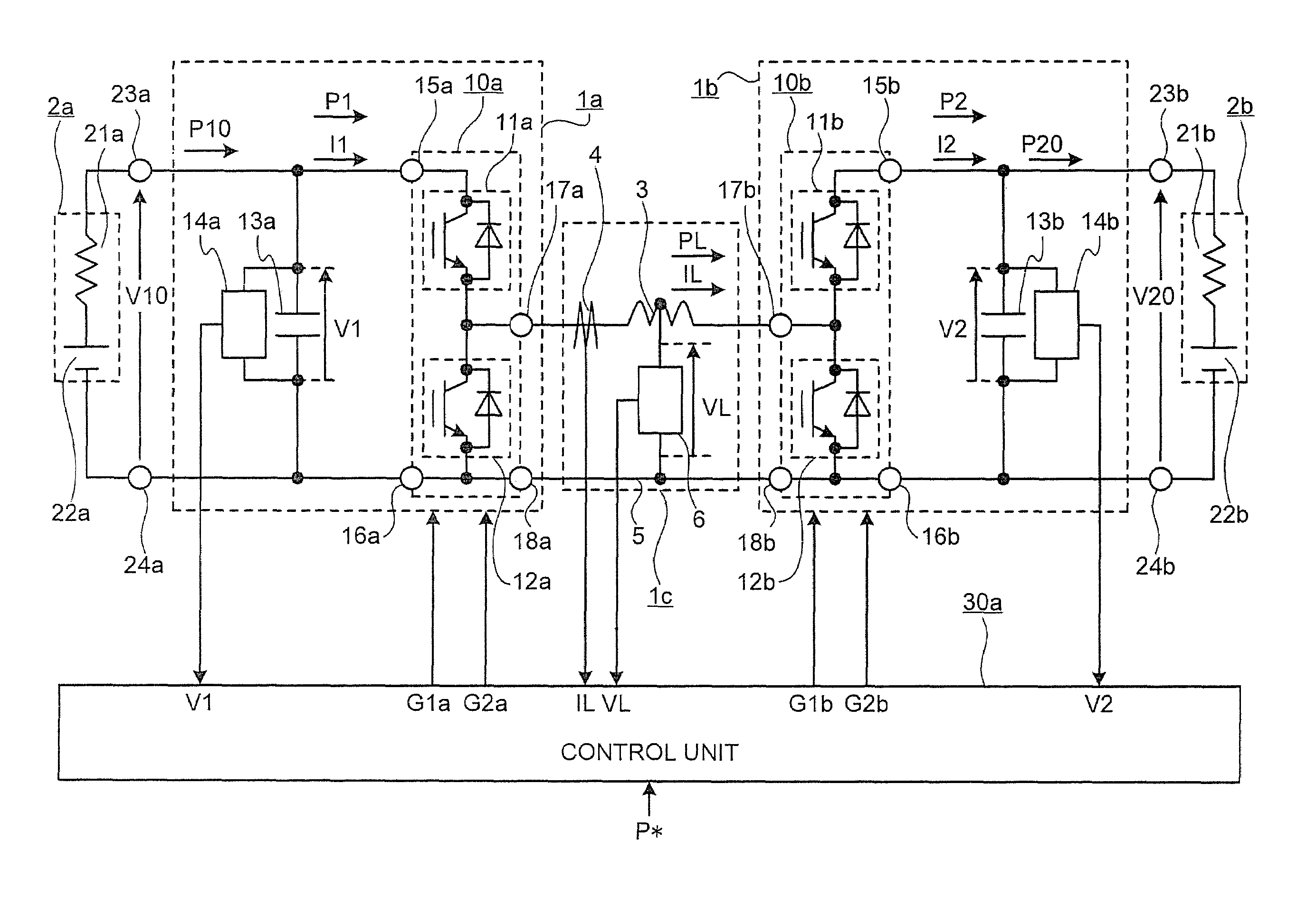
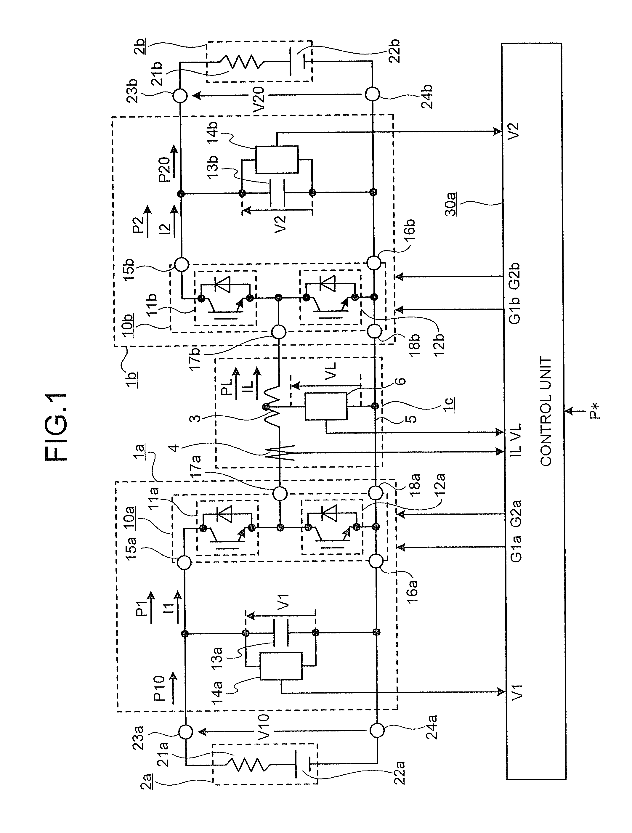
[0114]FIG. 1 is a configuration diagram of a bidirectional buck boost DC-DC converter according to the first embodiment. As shown in FIG. 1, a primary-side converting unit 1a is connected to input / output terminals 23a and 24a of a primary-side power supply 2a including a primary-side power supply impedance 21a and a primary-side power supply voltage source 22a, and is connected to a secondary-side converting unit 1b that is connected to input / output terminals 23b and 24b of a secondary-side power supply 2b including a secondary-side power supply impedance 21b and a secondary-side power supply voltage source 22b through a coupling unit 1c including a coupling reactor 3 and a connecting line 5.

[0115]The primary-side converting unit 1a includes a primary-side switching circuit 10a in which switching elements 11a and 12a are connected in series, a primary-side capacitor 13a that is connected in parallel with the primary-side switching circuit 10a, and a voltage detector 14a that detects...

second embodiment

[0175]A configuration of a bidirectional buck boost DC-DC converter according to the second embodiment of the present invention is explained in detail below with reference to the drawings. Only parts different from the bidirectional buck boost DC-DC converter in the first embodiment of the present invention are described below.

[0176]FIG. 16 is a configuration diagram of the bidirectional buck boost DC-DC converter according to the second embodiment of the present invention. In addition to the above first embodiment, the bidirectional buck boost DC-DC converter in the second embodiment includes a current detector 7a that detects the primary-side switching circuit current I1 and a current detector 7b that detects the secondary-side switching circuit current I2. Furthermore, a configuration of a control unit 30b has the following characteristics.

[0177]FIG. 17 is a diagram illustrating a configuration example of the control unit 30b according to the second embodiment of the present inve...

third embodiment

[0207]A configuration of a bidirectional buck boost DC-DC converter according to the third embodiment of the present invention is explained in detail below with reference to the drawings. The configuration in the third embodiment is based on that in the second embodiment. Only parts different from the bidirectional buck boost DC-DC converter in the second embodiment of the present invention are described below.

[0208]FIG. 27 is a configuration diagram of the bidirectional buck boost DC-DC converter according to a third embodiment of the present invention. In the bidirectional buck boost DC-DC converter in the third embodiment, the current detector 7a for detecting the primary-side switching circuit current I1 and the current detector 7b for detecting the secondary-side switching circuit current I2 that are provided in the configuration in the second embodiment are omitted. Furthermore, a configuration of a control unit 30c has the following characteristics.

[0209]FIG. 28 is a diagram ...


PUM


Abstract

According to the present invention, a bidirectional buck boost DC-DC converter can be obtained, in which power can flow bidirectionally from a primary side to a secondary side and from the secondary side to the primary side, regardless of a magnitude relation between a secondary-side voltage and a primary-side voltage in a state where different DC voltage sources are connected to the primary side and the secondary side in the DC-DC converter. A direction and a magnitude of the power can be automatically controlled to a desired value continuously on instantaneous value basis.

Description

TECHNICAL FIELD[0001]The present invention relates to a DC-DC converter that is used when direct-current voltage sources are connected to each other, and is applicable to, for example, an electric vehicle or the like on which a power storage device is mounted.BACKGROUND ART[0002]Conventionally, a technology has been known, in which a power storage device such as a secondary battery or an electric double-layer capacitor is applied to a railway system, and kinetic energy of a vehicle is effectively used by storing surplus regenerative power generated when braking the vehicle and using the stored power when the vehicle is accelerated. In this case, a buck boost converter (hereinafter, a bidirectional buck boost DC-DC converter) capable of controlling power in bidirectional directions is used for connecting a direct-current wire and the power storage device (for example, Patent Document 1).[0003]Patent Document 1: Japanese Patent Application Laid-open No. 2005-206111[0004]However, the b...

Claims


Application Information

Patent Timeline
Patent Type & Authority Patents(United States)
IPC IPC(8): B60L1/00H02J1/10H02J1/12H02J7/34
CPCH02M3/1582H02M3/1588H02M2001/0012Y10T307/511Y10T307/527Y10T307/544Y02B70/1466Y02B70/10H02M1/0012H02M3/139H02M3/33584
Inventor KITANAKA, HIDETOSHI
Owner MITSUBISHI ELECTRIC CORP
Why Eureka
Try Eureka