Pulse transformer with a choke part

Inactive Publication Date: 2010-05-25
TAIMAG CORP
5 Cites 9 Cited by

AI-Extracted Technical Summary

Problems solved by technology

Since the conventional pulse transformer requires two manual coil winding steps (respectively for the annular core 11 and the annular ...

Method used

[0032]It should be further noted herein that the annular core part 21 and the annular choke part 22 can be made such that magnetic flux direction of the annular choke part 22 is opposite to that of the annular core part 21. As a result, when the annular core part 21 and the annular choke part 22 are combined together concentrically, the magnetic fluxes in the annular core part 21 and the annular choke part 22 cancel out each other so that electromagnetic interference generated thereby is reduced, and overall inductance value of the pulse transformer is stabilized.
[0036]With reference to FIG. 9, the fourth preferred embodiment of a pulse transformer according to the present invention differs from the first preferred embodiment in that each of the annular core part 21c and the annular choke part 22c of the core unit 2c of the fourth preferred embodiment has inner and outer annular surfaces. The annular choke part 22c is disposed concentrically with the annular core part 21c such that the outer annular surface of the annular choke part 22c is disposed in contact with the inner annular surface of the annular core part 21c. In this case, a thickness of the pulse transformer is reduced as compared to the previous embodiments.
[0042]Since the annular core part 21 and the an...

Benefits of technology

[0012]The advantage of the present invention resides in that since the annular core part and the annular choke part are combined into one composite core unit before the coils are wound therear...

Abstract

A pulse transformer includes a core unit and a coil unit. The core unit includes an annular core part, and an annular choke part that is disposed in contact with the annular core part. The coil unit includes a plurality of coils, each of which is wound around both of the annular core part and the annular choke part.

Application Domain

Transformers/inductances coils/windings/connectionsTransformers/inductances magnetic cores +5

Technology Topic

Pulse transformerEngineering +2

Image

  • Pulse transformer with a choke part
  • Pulse transformer with a choke part
  • Pulse transformer with a choke part

Examples

  • Experimental program(1)

Example

[0025]Before the present invention is described in greater detail, it should be noted that like elements are denoted by the same reference numerals throughout the disclosure.
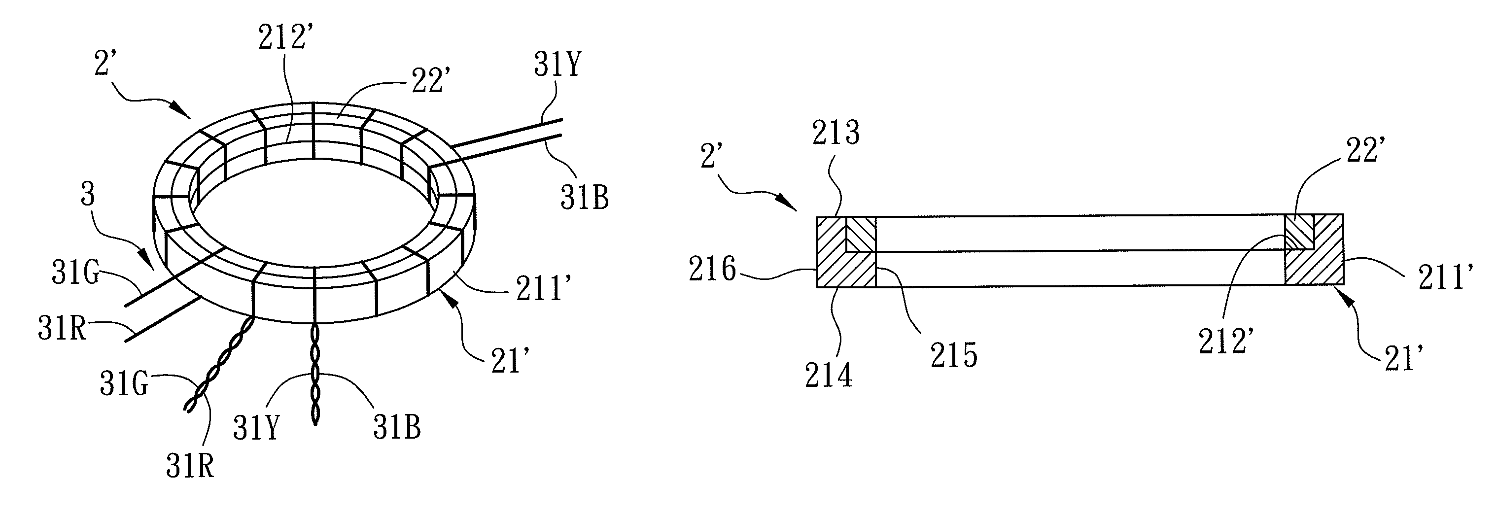
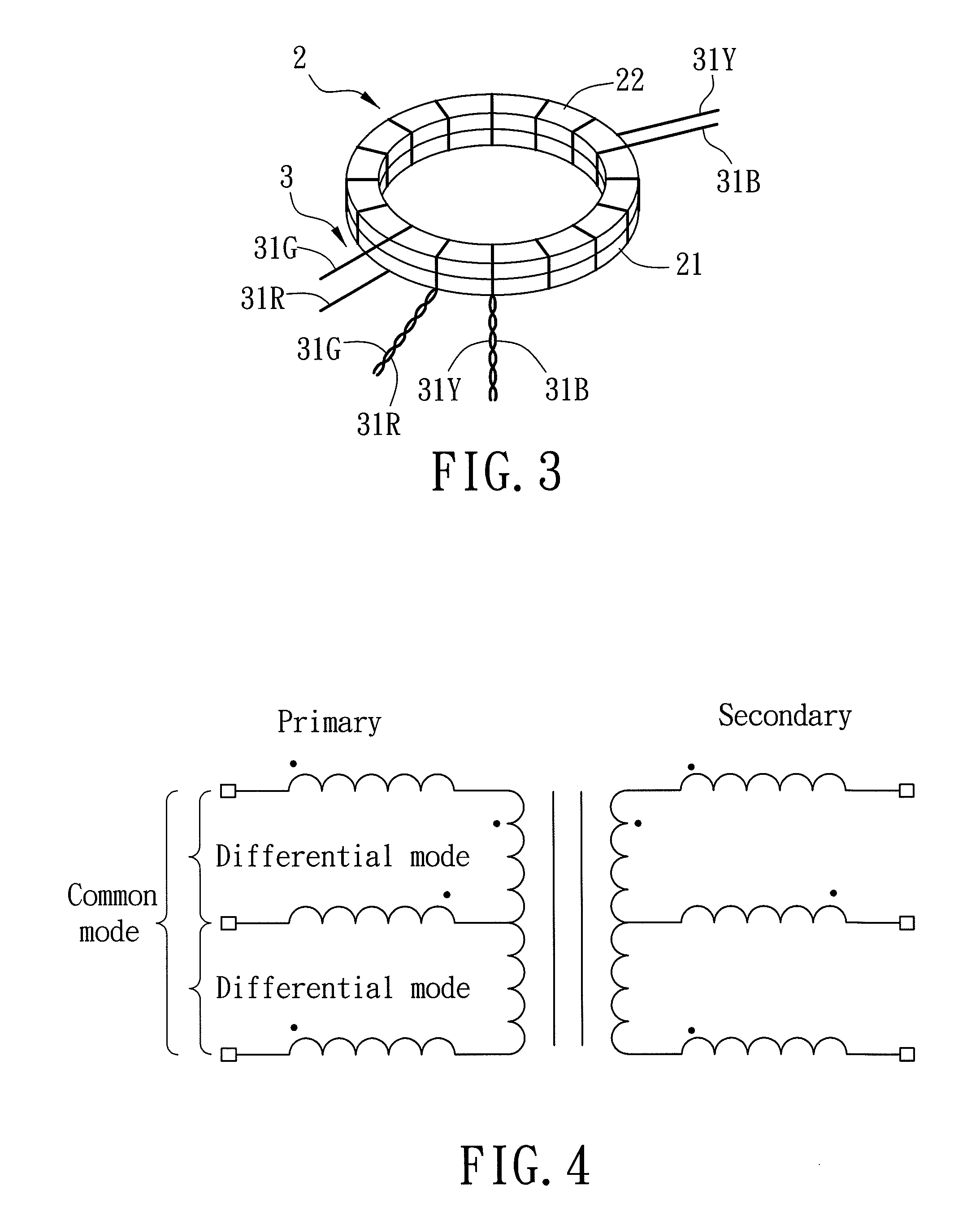
[0026]Referring to FIG. 3, the first preferred embodiment of a pulse transformer according to the present invention includes a core unit 2 and a coil unit 3.
[0027]The core unit 2 includes an annular core part 21, and an annular choke part 22 that is disposed in contact with the annular core part 21. The annular core part and the annular choke part 22 are made from a ferromagnetic material. In this embodiment, the annular core part 21 and the annular choke part 22 have substantially identical shapes, are stacked concentrically, and are respectively made from manganese and nickel.
[0028]The coil unit 3 includes a plurality of coils 31G, 31R, 31Y, 31B, which are hereinafter respectively referred to as a green coil 31G, a red coil 31R, a yellow coil 31Y, and a blue coil 31B. Each of the green, red, yellow, and blue coils 31G, 31R, 31Y, 31B is wound around both of the annular core part 21 and the annular choke part 22, such that six distinct terminals are formed in the pulse transformer. The six terminals are respectively formed by the green coil 31G, the red coil 31R, the yellow coil 31Y, the blue coil 31B, the green and red coils 31G, 31R twisted together, and the yellow and blue coils 31Y, 31B twisted together. The terminals formed by the green coil 31G, the red coil 31R, and the twisted green and red coils 31G, 31R cooperate to constitute a primary side of the pulse transformer, where the terminal formed by the twisted green and red coils 31G, 31R form a center tap. On the other hand, the terminals formed by the yellow coil 31Y, the blue coil 31B, and the twisted yellow and blue coils 31Y, 31B cooperate to constitute a secondary side of the pulse transformer, where the twisted yellow and blue coils 31Y, 31B form a center tap.
[0029]It should be noted herein that the number of windings for each of the green, red, yellow, and blue coils 31G, 31R, 31Y, 31B, and the choice of material for the annular core part 21 and the annular choke part 22 depend on the specification set forth for the particular product to be made. Since these should be readily appreciated by those skilled in the art, details of the same are omitted herein for the sake of brevity.
[0030]Shown in FIG. 4 is an equivalent circuit diagram for the first preferred embodiment. Not only does the first preferred embodiment achieve operation in a common mode as with the prior art, the first preferred embodiment can also operate in a differential mode.
[0031]It should be noted herein that the coil unit 3 of this embodiment includes four coils 31G, 31R, 31Y, 31B in order to form the center taps on each of the primary and secondary sides. However, for other embodiments where center taps are not required, the coil unit can include only two coils, and for those embodiments where only one center tap is required for one of the primary and secondary sides, the coil unit can include only three coils. In other words, the number of coils included in the coil unit is application dependent, and should not be considered a limitation to the scope of the present invention.
[0032]It should be further noted herein that the annular core part 21 and the annular choke part 22 can be made such that magnetic flux direction of the annular choke part 22 is opposite to that of the annular core part 21. As a result, when the annular core part 21 and the annular choke part 22 are combined together concentrically, the magnetic fluxes in the annular core part 21 and the annular choke part 22 cancel out each other so that electromagnetic interference generated thereby is reduced, and overall inductance value of the pulse transformer is stabilized.
[0033]With reference to FIG. 5 and FIG. 6, the second preferred embodiment of a pulse transformer according to the present invention differs from the first preferred embodiment in that the annular core part 21′ of the core unit 2′ of the second preferred embodiment includes an annular core body 211′ that is formed with an annular groove 212′. Furthermore, the annular choke part 22′ of the second preferred embodiment is disposed in the annular groove 212′.
[0034]In particular, the annular core body 211′ of the annular core part 21′ has first and second surfaces 213, 214 opposite to each other in a transverse direction, and inner and outer annular surfaces 215, 216 connecting the first and second surfaces 213, 214 and opposite to each other in radial directions transverse to the transverse direction. The annular groove 212′ is formed in the first surface 213 and the inner annular surface 215 of the annular core part 21′.
[0035]With reference to FIG. 7 and FIG. 8, the third preferred embodiment of a pulse transformer according to the present invention differs from the second preferred embodiment in that the annular groove 212″ of the core unit 2″ of the third preferred embodiment, within which the annular choke part 22″ is disposed, is formed in the first surface 213 and the outer annular surface 216 of the annular core part 21″.
[0036]With reference to FIG. 9, the fourth preferred embodiment of a pulse transformer according to the present invention differs from the first preferred embodiment in that each of the annular core part 21c and the annular choke part 22c of the core unit 2c of the fourth preferred embodiment has inner and outer annular surfaces. The annular choke part 22c is disposed concentrically with the annular core part 21c such that the outer annular surface of the annular choke part 22c is disposed in contact with the inner annular surface of the annular core part 21c. In this case, a thickness of the pulse transformer is reduced as compared to the previous embodiments.
[0037]With reference to FIG. 10, the fifth preferred embodiment of a pulse transformer according to the present invention differs from the first preferred embodiment in that the core unit 2d of the fifth preferred embodiment includes two of the annular choke parts 22. The annular core part 21 and the annular choke parts 22 are stacked concentrically such that the annular core part 21 is interposed between the annular choke parts 22.
[0038]From an actual Internet Protocol (IP) transmission test conducted for the preferred embodiments previously disclosed, it was verified that the pulse transformer according to the present invention complies with the standard set forth for transmission distances of over 100 meters, since no packet loss occurred for one hundred thousand packets transmitted over a transmission distance of 200 meters under a transmission rate of 1 Gbps in the IP transmission test.
[0039]FIG. 11 illustrates a method for manufacturing the pulse transformer of the present invention. The first preferred embodiment shown in FIG. 3 is used for illustration purposes. First, the annular core part 21 and the annular choke part 22 are prepared (step 4) by, for example, sintering, which is known in the art. Second, the annular core part 21 and the annular choke part 22 are combined concentrically into one composite core unit (step 5). Optionally, the annular core part 21 and the annular choke part 22 are combined together using an adhesive. Lastly, the plurality of coils 31G, 31R, 31Y, 31B are wound around the composite core unit 2 (step 6).
[0040]In summary, the pulse transformer according to the present invention has the following advantages:
[0041]1. Simplified Winding Process:
[0042]Since the annular core part 21 and the annular choke part 22 are combined into one composite core unit 2 before the coils 31G, 31R, 31Y, 31B are wound therearound, the pulse transformer of the present invention only requires one manual coil winding step, as compared to two manual coil winding steps in the prior art, thereby simplifying the fabrication of the pulse transformer of the present invention.
[0043]2. Differential Operation Mode:
[0044]By winding after combining the concentrically disposed annular core part 21 and the annular choke part 22 into a composite unit, the pulse transformer of the present invention can operate under both a differential mode and a common mode, as compared to operation only under the common mode in the prior art, thereby enhancing the applicability of the pulse transformer of the present invention.
[0045]3. Low Electromagnetic Interference and Stable Inductance Value:
[0046]Since the annular core part 21 and the annular choke part 22 can be made such that magnetic flux direction of the annular choke part 22 is opposite to that of the annular core part 21, when the annular core part 21 and the annular choke part 22 are combined together concentrically, the magnetic fluxes in the annular core part 21 and the annular choke part 22 cancel out each other so that electromagnetic interference generated thereby is reduced, and overall inductance value of the pulse transformer is stabilized.
[0047]While the present invention has been described in connection with what are considered the most practical and preferred embodiments, it is understood that this invention is not limited to the disclosed embodiments but is intended to cover various arrangements included within the spirit and scope of the broadest interpretation so as to encompass all such modifications and equivalent arrangements.

PUM

no PUM

Description & Claims & Application Information

We can also present the details of the Description, Claims and Application information to help users get a comprehensive understanding of the technical details of the patent, such as background art, summary of invention, brief description of drawings, description of embodiments, and other original content. On the other hand, users can also determine the specific scope of protection of the technology through the list of claims; as well as understand the changes in the life cycle of the technology with the presentation of the patent timeline. Login to view more.

Similar technology patents

Heat sink fabrication method

InactiveUS20130319064A1simplify fabrication processreduce tooling cost
Owner:DONG GUAN YUNG TENG ELECTRONICS PROD

Method for fabricating memory device

ActiveUS9070753B1reduce process variation and fabricating costsimplify fabrication process
Owner:MACRONIX INT CO LTD

Variable optical attenuator

InactiveUS20050013580A1compact sizesimplify fabrication process
Owner:LG ELECTRONICS INC

Projection system and light-homogenizing device adjustment element

ActiveUS20140185022A1decrease number of componentsimplify fabrication process
Owner:CORETRONIC

Classification and recommendation of technical efficacy words

  • simplify fabrication process

Multi-beam deflector array device for maskless particle-beam processing

ActiveUS20080203317A1simplify fabrication processreduce in size
Owner:INSTITUT FUER MIKROELEKTRONIK STUTTGART +1

Method of fabricating organic light emitting display

InactiveUS20050264184A1improve reliability of displaysimplify fabrication process
Owner:SAMSUNG DISPLAY CO LTD

Circuit board with optoelectronic component embedded therein

ActiveUS20070104412A1simplify fabrication processreduces fabrication difficulty
Owner:PHOENIX PRECISION TECH CORP

Flexible substrate and method for fabricating flexible display devicve having the same

ActiveUS20110062444A1simplify fabrication processprevent deformation
Owner:LG DISPLAY CO LTD

Electrophoretic display device and method of fabrication thereof

ActiveUS20120008191A1reduce fabrication costsimplify fabrication process
Owner:LG DISPLAY CO LTD
Why Eureka
Try Eureka