Heat sink fabrication method

Inactive Publication Date: 2013-12-05
DONG GUAN YUNG TENG ELECTRONICS PROD
View PDF9 Cites 0 Cited by
  • Summary
  • Abstract
  • Description
  • Claims
  • Application Information

AI Technical Summary

Benefits of technology

[0007]The present invention has been accomplished under the circumstances in view. It is one object of the present invention to provide a heat sink fabrication method, which is practical for making a heat sink that can efficiently dissipate waste heat from a heat source w

Problems solved by technology

The material and tooling costs of this design of heat sink are high.
The application of this design of heat sink is also limited.
It cannot be used for dissipating heat from certain chips.
However, increasing the height or de

Method used


Image

  • Heat sink fabrication method
  • Heat sink fabrication method
  • Heat sink fabrication method

Examples


Example

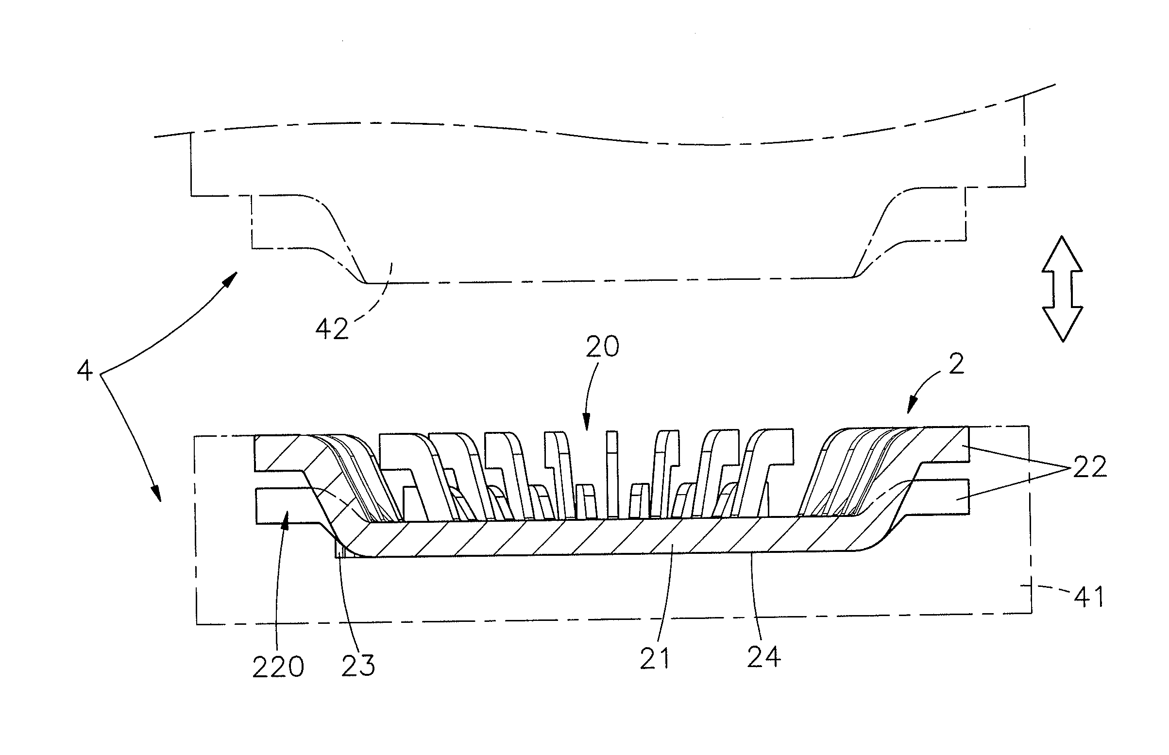
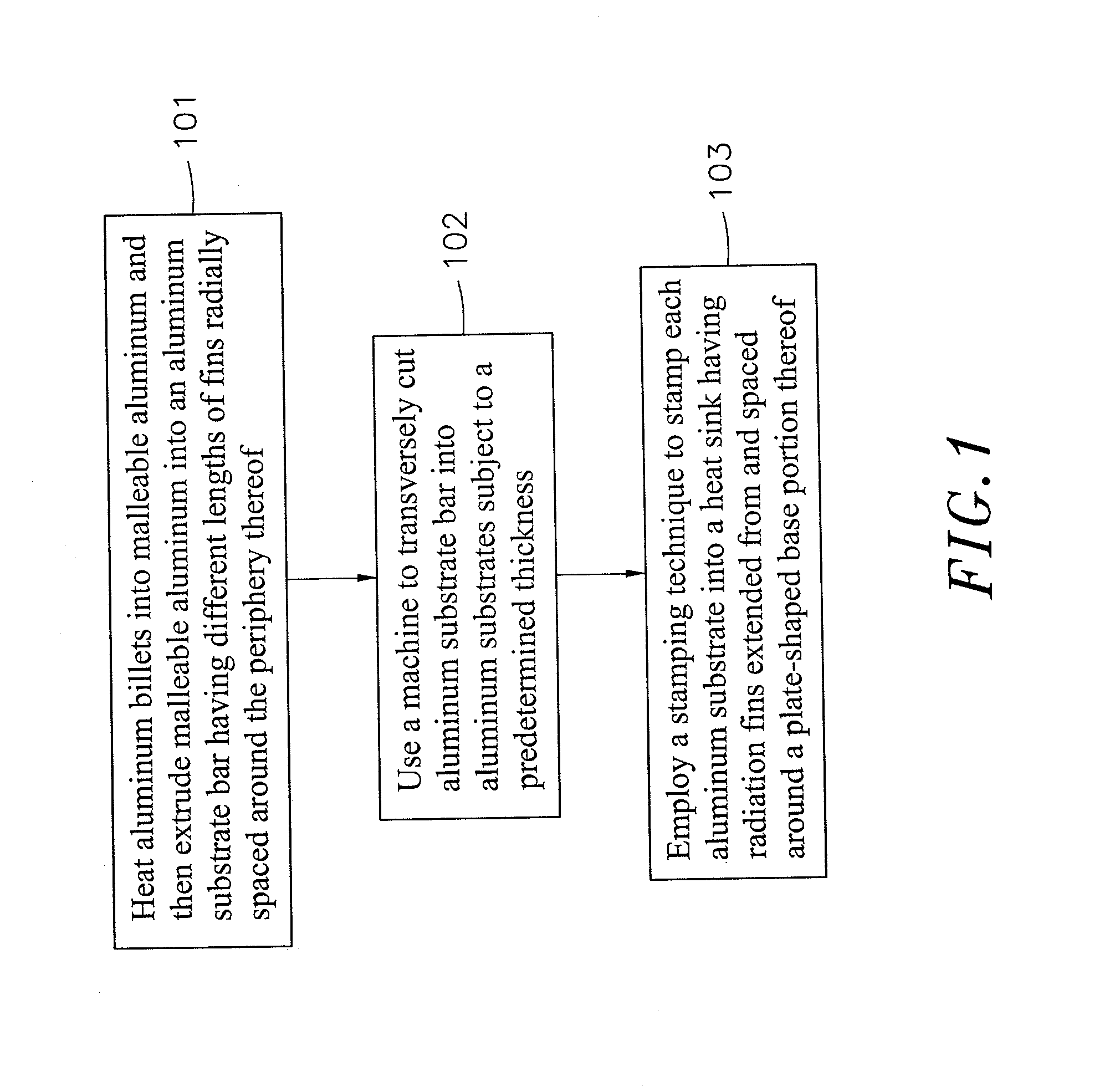
[0023]Referring to FIGS. 1-6, a heat sink fabrication method in accordance with the present invention comprises the steps of:[0024](101) heating aluminum billets into malleable aluminum 1 and then extruding malleable aluminum 1 into an aluminum substrate bar 11 having different lengths of fins 111 radially spaced around the periphery thereof;[0025](102) using a machine to transversely cut the aluminum substrate bar 11 into multiple aluminum substrates 11 subject to a predetermined thickness; and[0026](103) employing a stamping technique to stamp each aluminum substrate 11 into a heat sink 2 having radiation fins 22 extended from and spaced around a plate-shaped base portion 21 thereof.

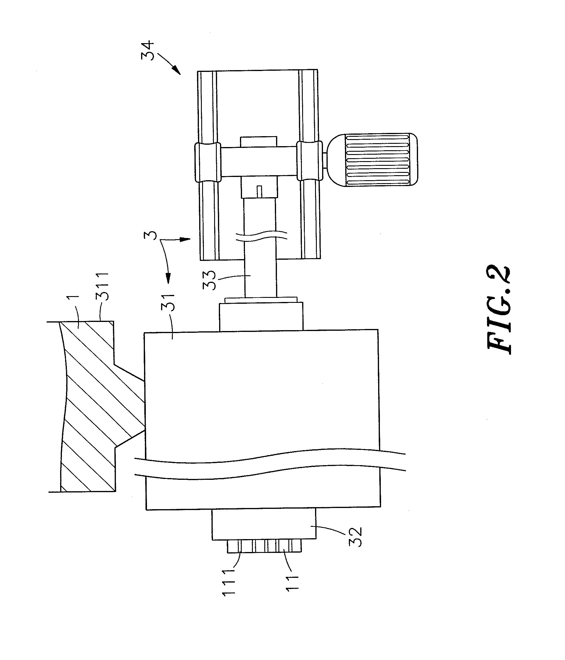
[0027]During fabrication, aluminum billets are prepared and heated into a molten condition, and then molten aluminum 1 is put in a hopper 311 of an extruding machine 3 and fed into an extruder unit 31 where aluminum 1 is maintained in a malleable condition, and a screw 33 is rotated by a motor drive 34...


PUM

PropertyMeasurementUnit
Thicknessaaaaaaaaaa
Thicknessaaaaaaaaaa
Lengthaaaaaaaaaa

Abstract

A heat sink fabrication method includes the step of heating aluminum billets into malleable aluminum and then extruding malleable aluminum into an aluminum substrate bar having different lengths of fins radially spaced around the periphery thereof, the step of using a machine to transversely cut the aluminum substrate bar into multiple aluminum substrates subject to a predetermined thickness, and the step of employing a stamping technique to stamp each aluminum substrate into a heat sink having radiation fins extended from and spaced around a plate-shaped base portion thereof.

Description

BACKGROUND OF THE INVENTION[0001]1. Field of the Invention[0002]The present invention relates to heat sink fabrication technology and more particularly, to a heat sink fabrication method for making a heat sink using extruding and stamping techniques that simplifies heat sink fabrication, reduces tooling costs, and ensures high dimensional precision of the product.[0003]2. Description of the Related Art[0004]Following fast development of computer technology, powerful, high-speed, inexpensive computers with large capacities have been continuously created. In consequence, computer related applications have also been well developed. As clock frequencies in digital circuits and voltage applied increase, the heat generated by components running at the higher performance levels also increases. It requires more effective cooling to avoid damaging the hardware by overheating. Many heat sinks have been created for the purposes of cooling computer components.[0005]A heat sink may be directly a...

Claims


Application Information

Patent Timeline
IPC IPC(8): B23P15/26
CPCH01L23/367H01L23/467H01L21/4871B23P15/26F28F3/02H01L2924/0002B23P2700/10H01L2924/00
Inventor LIN, YI-KUN
Owner DONG GUAN YUNG TENG ELECTRONICS PROD
Why Eureka
Try Eureka