
System and method for recording and reproducing holographic interferogram with optical servo

a technology of optical servo and holographic storage, which is applied in the field of system and method for recording and reproducing holographic storage, can solve the problems of difficult application to commercial optical storage products, and inability to achieve holographic storag

Inactive Publication Date: 2010-05-25
IND TECH RES INST
View PDF11 Cites 13 Cited by
  • Summary
  • Abstract
  • Description
  • Claims
  • Application Information

AI Technical Summary

Benefits of technology

This approach enhances storage capacity by enabling the generation and recording of holographic interferograms in multiple layers, improving the efficiency and practicality of holographic storage technology while reducing the need for expensive components and complex servomechanisms.

Problems solved by technology

However, many factors make it difficult to be applied to commercial optical storage products.
Meanwhile, photo-refractive crystals serving as holographic storage media are too expensive, so that the development of holographic storage is limited.
However, to a continuously moving holographic storage media, it is very difficult to adjust the position and the direction of the reflecting mirror set on time.
They put forward a mechanism for a reflective holographic storage media, but they also failed to provide optical servomechanism for a continuously moving holographic storage media.
But the holographic interferogram is recorded only on a single layer, so the capacity of storage is limited.

Method used


Image

  • System and method for recording and reproducing holographic interferogram with optical servo
  • System and method for recording and reproducing holographic interferogram with optical servo
  • System and method for recording and reproducing holographic interferogram with optical servo

Examples


first embodiment

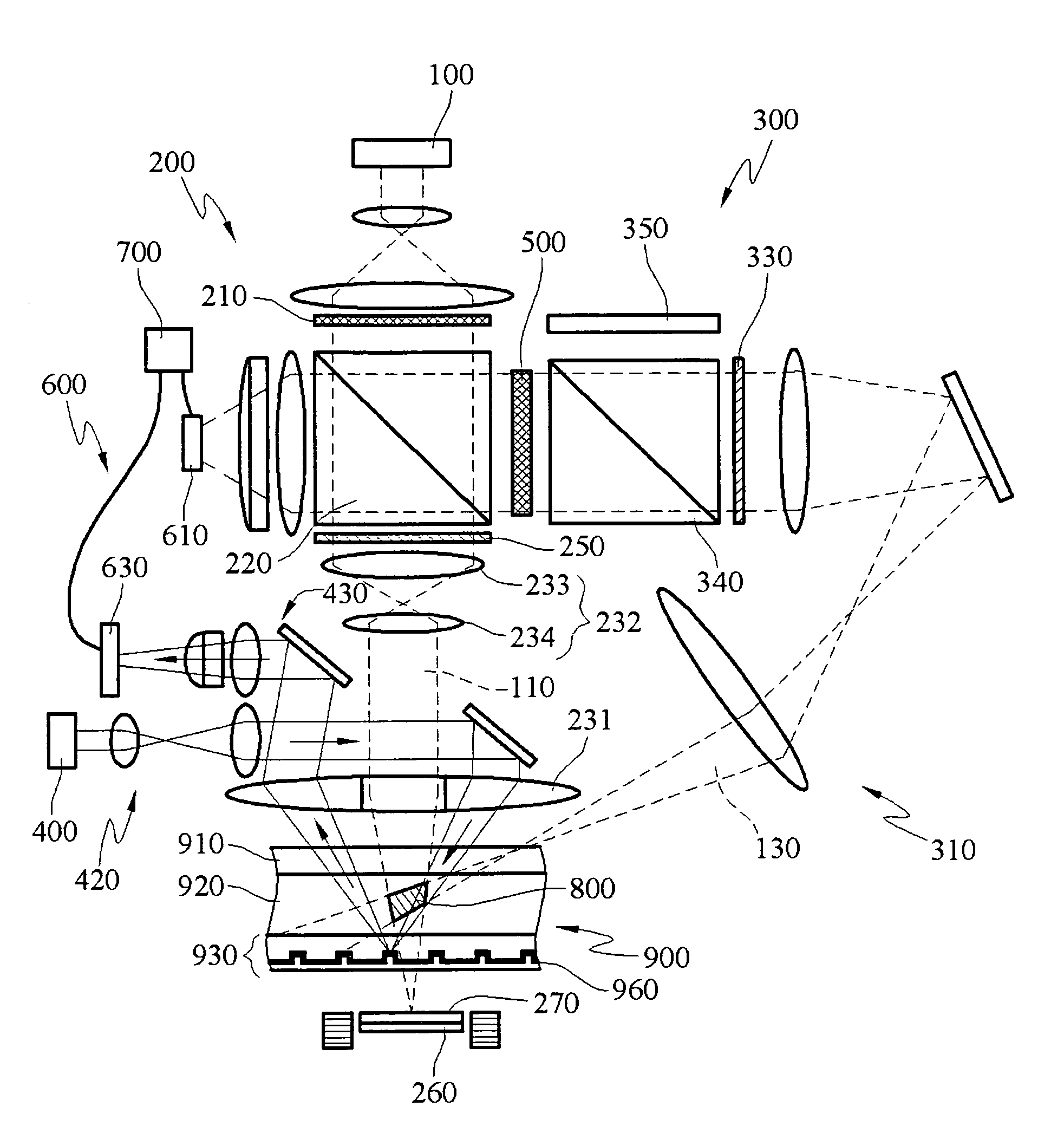
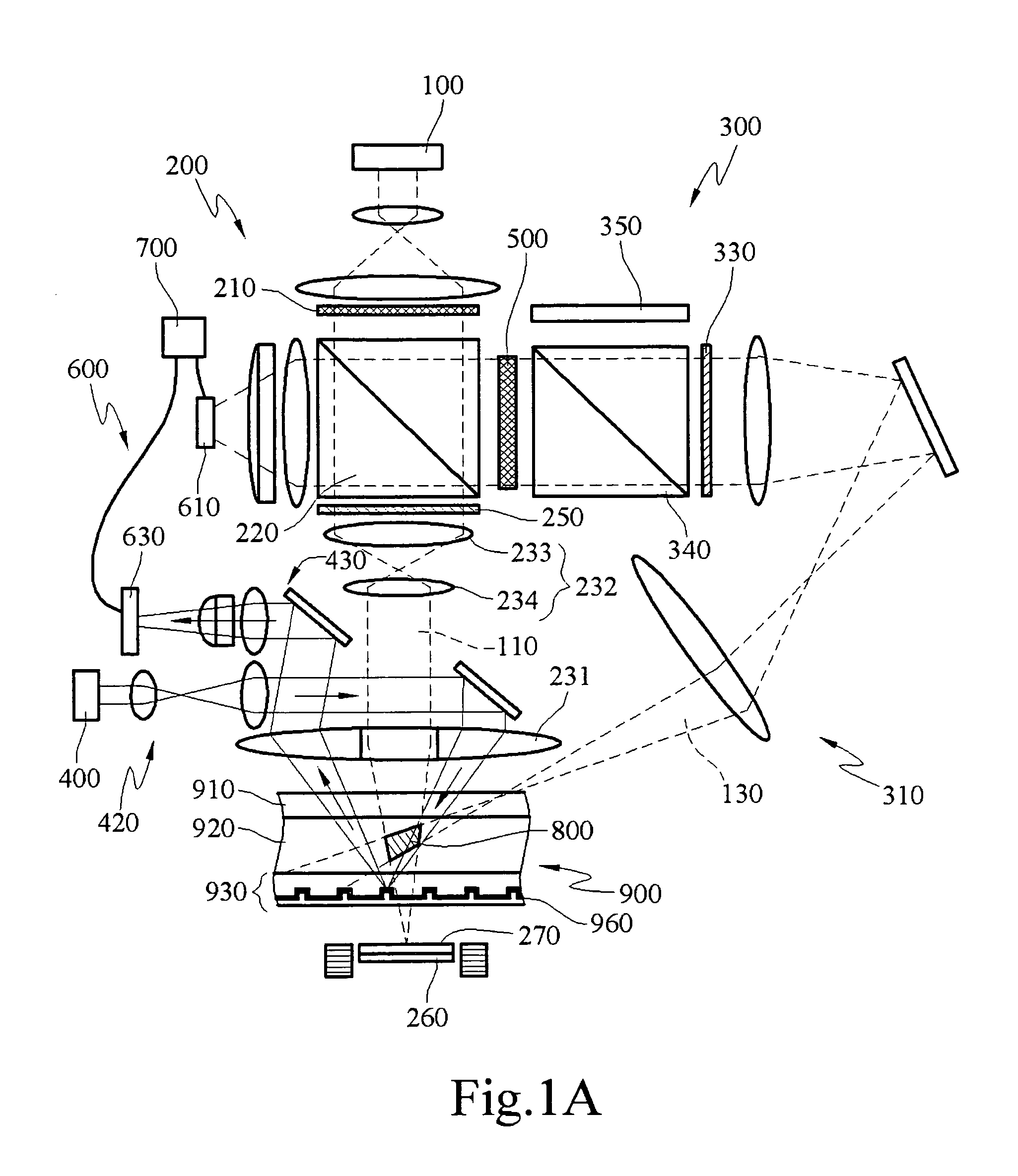
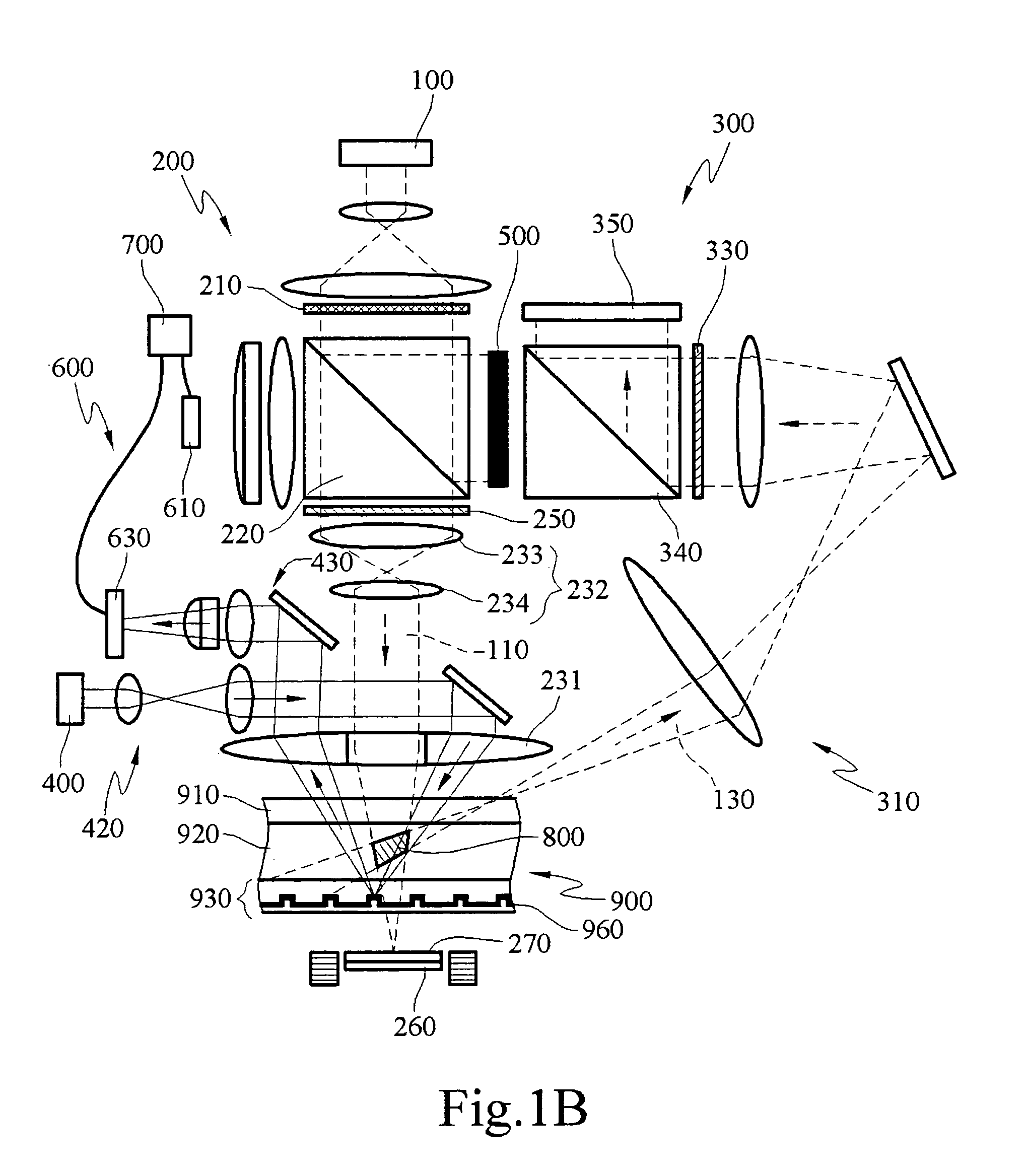
[0050]A light source 100 emits coherence light. The coherence light is split into a reference beam 110 and a signal beam 130 after passing through a first light guiding portion 200. The reference beam 110 is guided by the first light guiding portion 200 to be projected to the holographic storage media 900 in a first incidence direction. In the first embodiment, the first incidence direction is a direction perpendicular extending into the holographic storage media 900. The signal beam 130, split by the first light guiding portion 200, is projected to a spatial light modulator (SLM) 500. The signal beam 130 is modulated by the SLM 500, and then guided by a second light guiding portion 300 to be projected to the holographic storage media 900 in a second incidence direction. The polarization of the signal beam 130 is the same as that of the reference beam 110, such that the reference beam 110 and the signal beam 130 interfere with each other in the recording layer 920 of the holographic...

fourth embodiment

[0071]FIG. 5B is a schematic view of the present invention, showing the system reproducing the holographic interferogram.

[0072]When the reference beam 110 passing through the first phase delay film 250 is projected to the holographic interferogram 800 and is reflected by the reflecting mirror. A fourth phase delay film 270 is adhered to one side of the reflecting mirror, the reference beam 110 will pass through the fourth phase delay film 270 twice, such that the polarization of the reference beam 110 is converted to P polarization. When the reference is reflected and projected to the holographic interferogram 800 again, a conjugate reproducing beam 150 is generated. The conjugate reproducing beam 150 travel back along the path of the signal beam 130, and passes through the first polarizing splitter 340 through the lenses and reflecting mirror sets 310.

[0073]A two-dimensional image sensor 350 is located on one side of the first polarizing splitter 340 for receiving the reproducing b...

fifth embodiment

[0076]Therefore, the second light guiding portion 300 of the fifth embodiment has to be modified correspondingly. After the signal beam 130 passing through the second phase delay film 330 and being projected to the SLM 500, it is reflected and then projected to the first polarizing splitter 340.

[0077]The polarization of the signal beam 130 is converted from P polarization to S polarization after passing through the second phase delay film 330, such that the signal beam 130 is reflected by the first polarizing splitter 340 to be projected to the lenses and reflecting mirror sets 310. Then the signal beam 130 is projected to the holographic storage media 900 along the second incidence direction, and interferes with the reference beam 110, to generate the holographic interferogram 800.

[0078]FIG. 6B is a schematic view of the fifth embodiment of the present invention, showing the system reproducing the holographic interferogram.

[0079]When the reference beam 110 passing through the first...


PUM


Abstract

A system and method for recording and reproducing holographic interferogram with servos. A servo process is provided by the system and method to continuously record a holographic interferogram in a holographic recording medium with servo trace layers. Also, by the servo process, the intensity distribution of a reference beam is monitored, which is reflected by a reflecting mirror disposed on the other side of the holographic recording medium. By analyzing the distribution, one can adjust the distance and the incidence angle between the reflection mirror and the reference beam. Moreover, a plurality of servo tracks on different layers are provided for recording the holographic interferogram on different layers of holographic recording medium.

Description

CROSS-REFERENCE TO RELATED APPLICATIONS[0001]This non-provisional application claims priority under 35 U.S.C. §119(a) on Patent Application No(s). 094147743 filed in Taiwan, R.O.C. on Dec. 30, 2005, the entire contents of which are hereby incorporated by reference.BACKGROUND OF THE INVENTION[0002]1. Field of Invention[0003]The present invention relates to a system and method for recording and reproducing holographic storage, and more particularly, to a system and method which has an optical servo.[0004]2. Related Art[0005]Today, the storage capacity of commercial blue-ray disks rarely exceeds 100 GBytes, and various approaches to achieve super-high storage capacity have been widely researched and developed. The holographic disk is the most important approach of all. The holographic storage technology has been developed for long time. However, many factors make it difficult to be applied to commercial optical storage products. For example, in the early days holographic experiments ha...

Claims


Application Information

Patent Timeline
Patent Type & Authority Patents(United States)
IPC IPC(8): G03H1/26
CPCG11B7/0065G11B7/1275G11B7/0938G11B7/00781G03H2001/2615
Inventor LIN, CHIH-MINGLAN, YUNG-SUNGKUO, CHEN-IJENG, TZUAN-RENLO, FENG-HSIANG
Owner IND TECH RES INST
Learn More