
Integrated power conditioning system and housing for delivering operational power to a motor

a power conditioning system and integrated technology, applied in the direction of dc circuit to reduce harmonics/ripples, electric energy, energy industry, etc., can solve the problem that fixed frequency ac power is often not suitable for end use in consuming facilities, and achieve the effect of saving power consumption, cost, and siz

Inactive Publication Date: 2010-05-25
ROCKWELL AUTOMATION TECH
View PDF3 Cites 22 Cited by
  • Summary
  • Abstract
  • Description
  • Claims
  • Application Information

AI Technical Summary

Benefits of technology

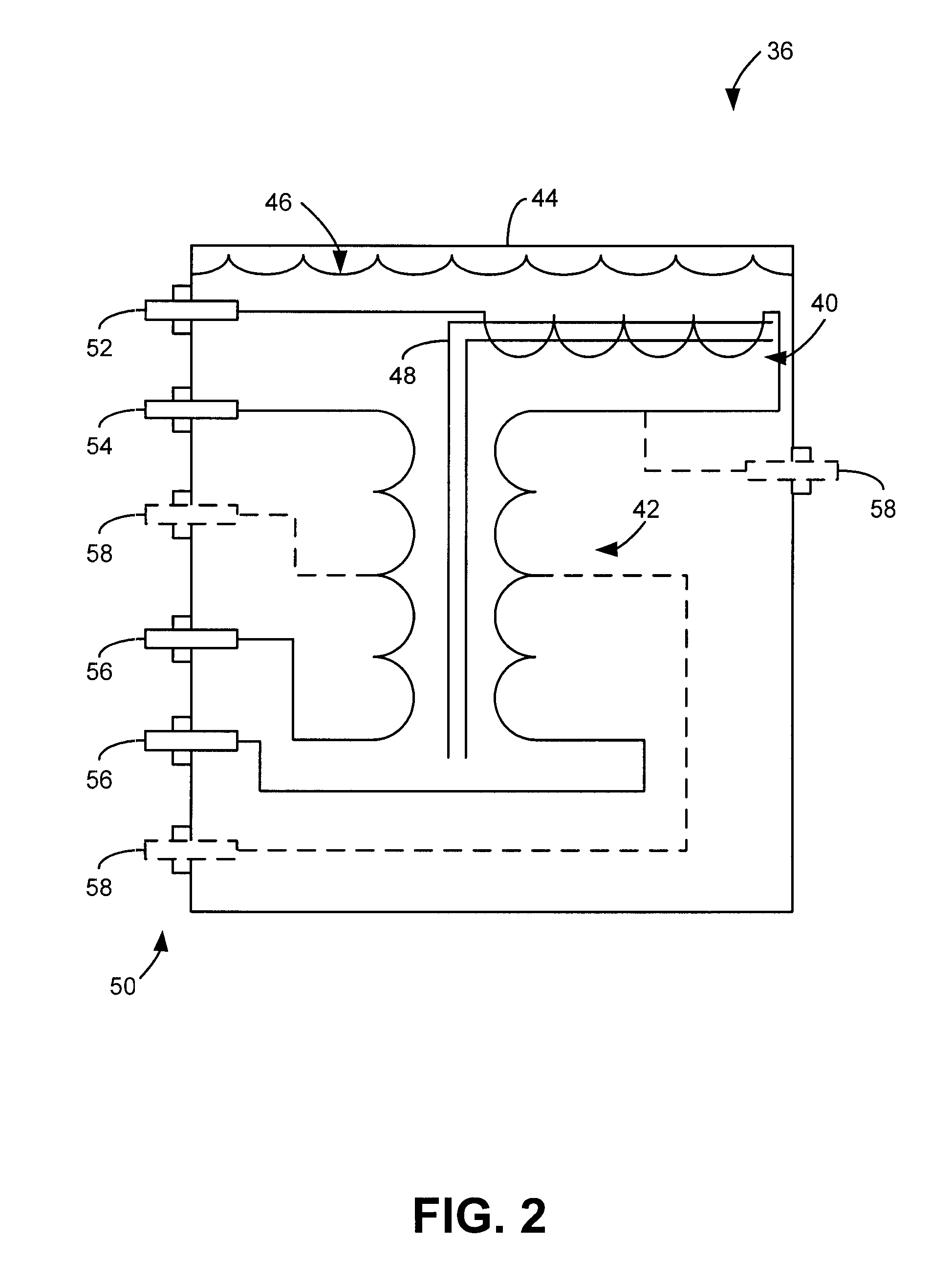
The present invention provides an integrated power conditioning system for delivering power to a motor enclosed in a common housing. This results in cost, size, and power consumption savings. The system includes a filter and transformer arranged together in a single housing, with a shared metal core extending through the windings of both components. The device filters the input power and delivers it to the transformer, which then isolates the input from the output and delivers conditioned power to power the motor. The technical effects of this invention include improved efficiency, reduced size and cost, and improved power delivery for driving motors.

Problems solved by technology

Despite being efficiently distributable, fixed frequency AC power is often not suitable for end use in consuming facilities.
These filters are particularly important when the distance between the output of the motor drive unit and the motor input is significant because power stability issues raised by reflected waves are further exacerbated over these long distances.

Method used


Image

  • Integrated power conditioning system and housing for delivering operational power to a motor
  • Integrated power conditioning system and housing for delivering operational power to a motor
  • Integrated power conditioning system and housing for delivering operational power to a motor

Examples


Embodiment Construction

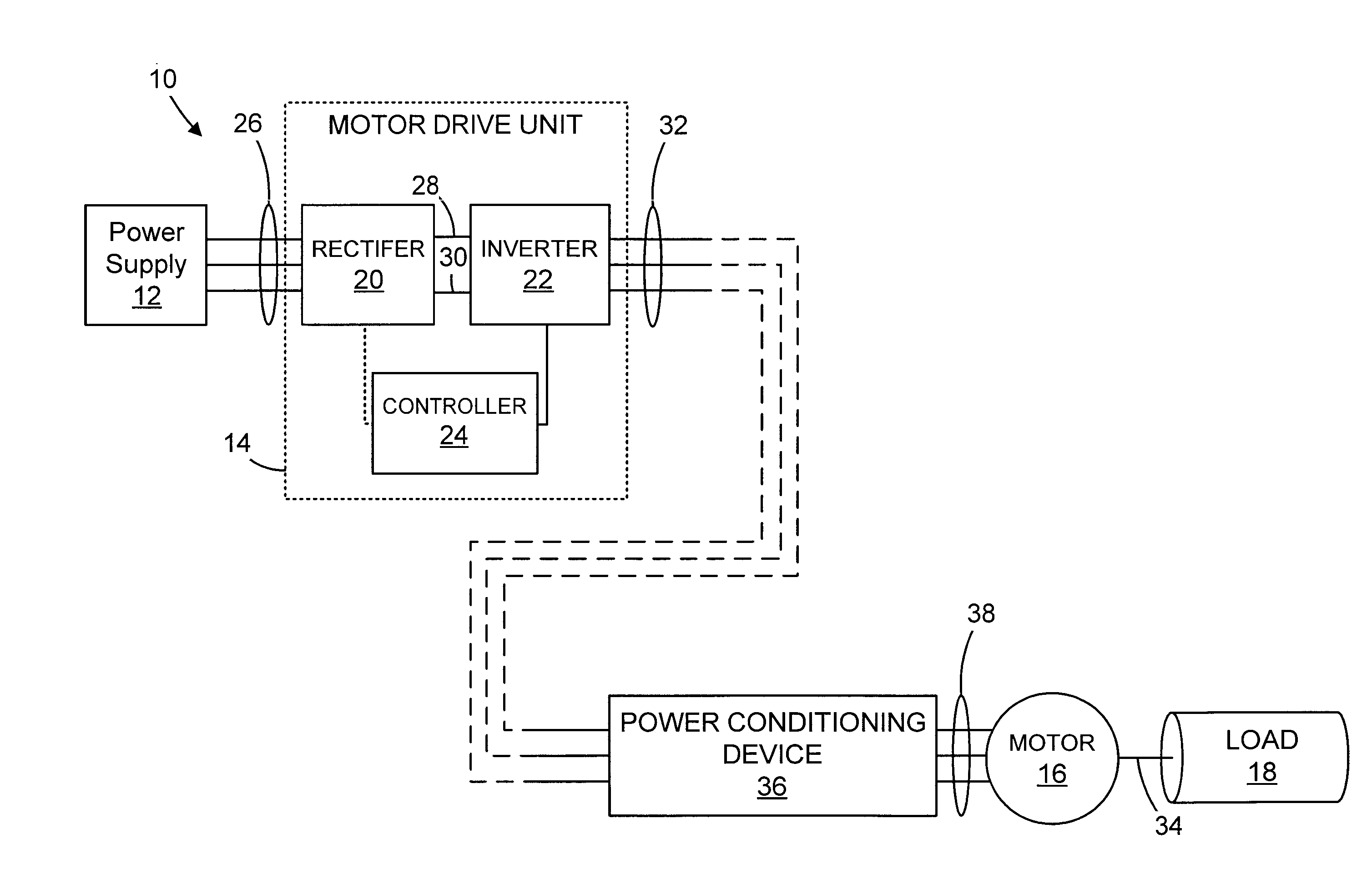
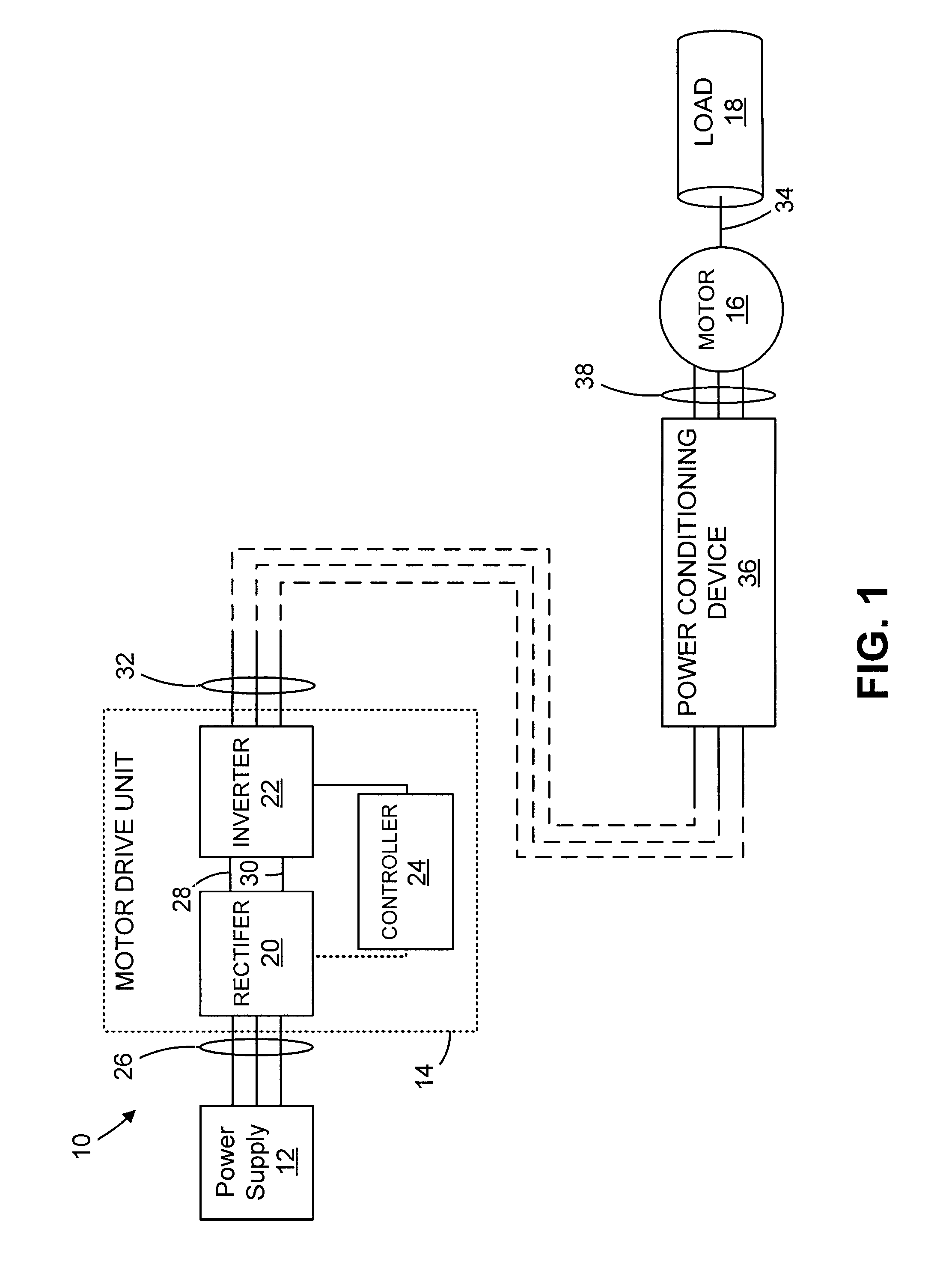
[0030]Referring now to FIG. 1, the present invention will be described in the context of a motor control system 10. The motor control system 10 includes a power supply 12 and a motor drive unit 14. The power supply 12 provides power to the motor drive unit 14 that, in turn, converts the power to a more usable form for a three-phase motor 16 that drives an associated load 18.

[0031]The motor drive unit 14 includes variety of components, such as a rectifier 20, an inverter 22, and a controller 24. During operation, the power supply 12 provides three-phase AC power, for example, as received from a utility grid over transmission power lines 26. However, it is also contemplated that the power supply 12 may be designed to deliver single-phase power. In either case, the nominal line voltage delivered by the power supply 12 is dependent on the particulars of the motor 16, load 18, and power available to the power supply 12 to drive the motor drive 14. For example, as addressed above, the pow...


PUM


Abstract

A device for conditioning power delivered to operate a motor is disclosed. The device includes a sealed housing having at least one input terminal extending through the housing and configured to receive an input power and at least one output terminal extending through the housing and configured to deliver an output power conditioned to power a motor coupled to the output terminal. The device also includes a filter inductor arranged in the housing and that has an input configured to receive the input power from the input terminal. The filter inductor output terminal has a tap that is extended through the housing to allow coupling of various external filter components, such as resistors capacitors and inductors. Accordingly, the filter inductor is configured to suppress voltage changes in the input power and deliver a filtered power to an output of the filter inductor. A transformer is included that is arranged in the housing and has an input configured to receive the filtered power from the output of the filter inductor. As such, the transformer is at least configured to electrically isolate the input terminal from the output terminal and deliver a conditioned power from an output of the transformer to the output terminal to power the motor coupled to the output terminal.

Description

CROSS-REFERENCE TO RELATED APPLICATIONS STATEMENT REGARDING FEDERALLY[0001]--SPONSORED RESEARCH OR DEVELOPMENT[0002]--BACKGROUND OF THE INVENTION[0003]The present invention relates generally to power conditioning systems for driving motors and, more particularly, to an integrated power conditioning system for delivering power suitable for driving a motor that may be enclosed in a common housing.[0004]Power plants are linked to power consuming facilities (e.g., buildings, factories, etc.) via utility grids designed so as to be extremely efficient in delivering massive amounts of power. To facilitate efficient distribution, power is delivered over long distances as fixed frequency three-phase alternating current (AC) power.[0005]Despite being efficiently distributable, fixed frequency AC power is often not suitable for end use in consuming facilities. In many applications, the power delivered by the utility must be converted or “conditioned” to a useable form. For example, motors and ...

Claims


Application Information

Patent Timeline
Patent Type & Authority Patents(United States)
IPC IPC(8): H02J1/02H02M1/12
CPCH02M7/003H01F27/02H01F27/04Y02P80/11H01F27/40Y02P80/10
Inventor SKIBINSKI, GARY L.WILKINS, JOHNHOADLEY, RICKGUSKOV, NICKBRAUN, DENNIS
Owner ROCKWELL AUTOMATION TECH
Learn More