System and method for reducing interferometric distortion and relative intensity noise in directly modulated fiber optic links

a technology of interferometric distortion and relative intensity noise, which is applied in the field of optical systems, can solve the problems of reducing the spur free dynamic range (sfdr) of the system, affecting the fidelity of the transmitted signal, and several undesirable properties, so as to minimize the ratio of interferometric intermodulation distortion and the ratio of relative intensity nois

Inactive Publication Date: 2010-05-25
RAYTHEON CO
View PDF19 Cites 8 Cited by
  • Summary
  • Abstract
  • Description
  • Claims
  • Application Information

AI Technical Summary

Problems solved by technology

During the modulation and transmission process, undesirable intermodulation products can be generated, corrupting the fidelity of the transmitted signal.
In addition, relative intensity noise (RIN) generated by the transmitter further reduces the spur free dynamic range (SFDR) of the system.
Many systems currently use this approach; however, it has several undesirable properties.
In particular, the manner by which the EO modulator is designed requires a relatively expensive polarization maintaining fiber for coupling the output of the CW laser to the EO modulator.
Secondly, the external modulator itself is fairly expensive, resulting in an impetus to replace it with a less costly solution.
Unfortunately, the directly modulated approach suffers from corruption of the transmission signal due to interferometric distortion.
The use of an optical isolator, however, increases the complexity of the optics needed to efficiently couple the emission of the diode laser to the optical fiber.
In addition, the diode laser generates relative intensity noise, which—although small in comparison to the signal—may affect applications where very high SFDR is required.

Method used


Image

  • System and method for reducing interferometric distortion and relative intensity noise in directly modulated fiber optic links
  • System and method for reducing interferometric distortion and relative intensity noise in directly modulated fiber optic links
  • System and method for reducing interferometric distortion and relative intensity noise in directly modulated fiber optic links

Examples


Embodiment Construction

[0020]Illustrative embodiments and exemplary applications will now be described with reference to the accompanying drawings to disclose the advantageous teachings of the present invention.

[0021]While the present invention is described herein with reference to illustrative embodiments for particular applications, it should be understood that the invention is not limited thereto. Those having ordinary skill in the art and access to the teachings provided herein will recognize additional modifications, applications, and embodiments within the scope thereof and additional fields in which the present invention would be of significant utility.

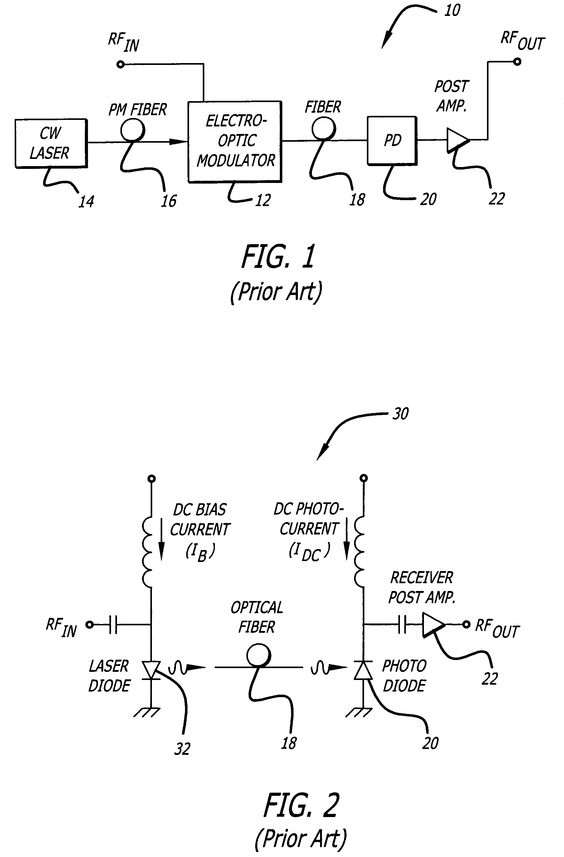
[0022]As mentioned above, the conventional method for reducing interferometric intermodulation distortion is to use an externally modulated link. FIG. 1 is a simplified schematic of an externally modulated analog fiber optic link 10 of conventional design and construction. In the transmission system 10 of FIG. 1, an input signal RFIN is modulated ont...


PUM


Abstract

A laser transmitter with a feedback control loop for minimizing noise. The novel laser transmitter includes a laser, an external reflector adapted to form an extended cavity to the laser, and a feedback control loop adapted to detect noise in the laser and in accordance therewith, adjust the optical phase of the extended cavity such that the noise is at a desired level. The optical phase of the extended cavity is adjusted by adjusting an operating parameter of the laser, such as its bias current. In an illustrative embodiment, the feedback control loop is adapted to compute the rate of change of the noise with respect to bias current and in accordance therewith, adjust the bias current of the laser such that relative intensity noise and interferometric intermodulation distortion are simultaneously minimized.

Description

BACKGROUND OF THE INVENTION[0001]1. Field of the Invention[0002]The present invention relates to optical systems. More specifically, the present invention relates to systems and methods for minimizing interferometric distortion and relative intensity noise in directly modulated fiber optic links.[0003]2. Description of the Related Art[0004]In a fiber optic transmission system, an RF (radio frequency) signal is often modulated onto an optical carrier and delivered subsequently to a remote site for additional processing via an optical link. During the modulation and transmission process, undesirable intermodulation products can be generated, corrupting the fidelity of the transmitted signal. In addition, relative intensity noise (RIN) generated by the transmitter further reduces the spur free dynamic range (SFDR) of the system. A maximal SFDR is desirable for many applications, such as the transmission of cable TV signals.[0005]A viable method for reducing intermodulation distortion—i...

Claims


Application Information

Patent Timeline
Patent Type & Authority Patents(United States)
IPC IPC(8): H04B10/04H01S3/00
CPCH04B10/504H01S5/06817
Inventor NG, WILLIE W.PERSECHINI, DAVID L.BUCKLEY, ROBERT H.
Owner RAYTHEON CO
Why Eureka
Try Eureka