
Temperature control unit for electronic component and handler apparatus

a technology of temperature control unit and electronic component, which is applied in the direction of domestic cooling apparatus, semiconductor/solid-state device details, instruments, etc., can solve the problems of dew condensation at the pipe of a movable area, and the response of heating during the switch from cooling to heating is not always satisfactory, and achieves excellent responsibility

Inactive Publication Date: 2010-06-01
NS TECH INC
View PDF14 Cites 29 Cited by
  • Summary
  • Abstract
  • Description
  • Claims
  • Application Information

AI Technical Summary

Benefits of technology

[0013]The present invention is performed in view of the above-mentioned problems, and the object of the present invention is to obtain a temperature control unit and a handler apparatus for an electronic component, which are excellent in responsibility during performing both of cooling and heating. Moreover, the object of the present invention is to obtain a temperature control unit and a handler apparatus, where dew condensation to a pipe of a movable part due to cooling is prevented. Further, the object of the present invention is also to obtain a temperature control unit and a handler apparatus, including a suction pad for vacuum-sucking the electronic component that is an object to be temperature-controlled, where the suction pad can suck the electronic component without sucking in the thermally conductive liquid discharged on the upper surface of the electronic component.

Problems solved by technology

Moreover, in a cooling system as in Patent document 3, including a compressor and a condenser, responsibility of heating during switching from cooling to heating was not always satisfactory.
Moreover, as for such a kind of conventional temperature control unit, there was a problem in that dew condensation occurred at a pipe of a movable area due to cooling.
Further, in a measuring hand of a handler apparatus integrally a having a function for transferring the electronic component and a function for cooling the electronic component being measured, there was also a problem in that a suction pad for sucking the electronic component may sucks in a thermally conductive liquid coated on the upper surface of the electronic component in order to improve thermal conductivity thereof.

Method used


Image

  • Temperature control unit for electronic component and handler apparatus
  • Temperature control unit for electronic component and handler apparatus
  • Temperature control unit for electronic component and handler apparatus

Examples


first embodiment

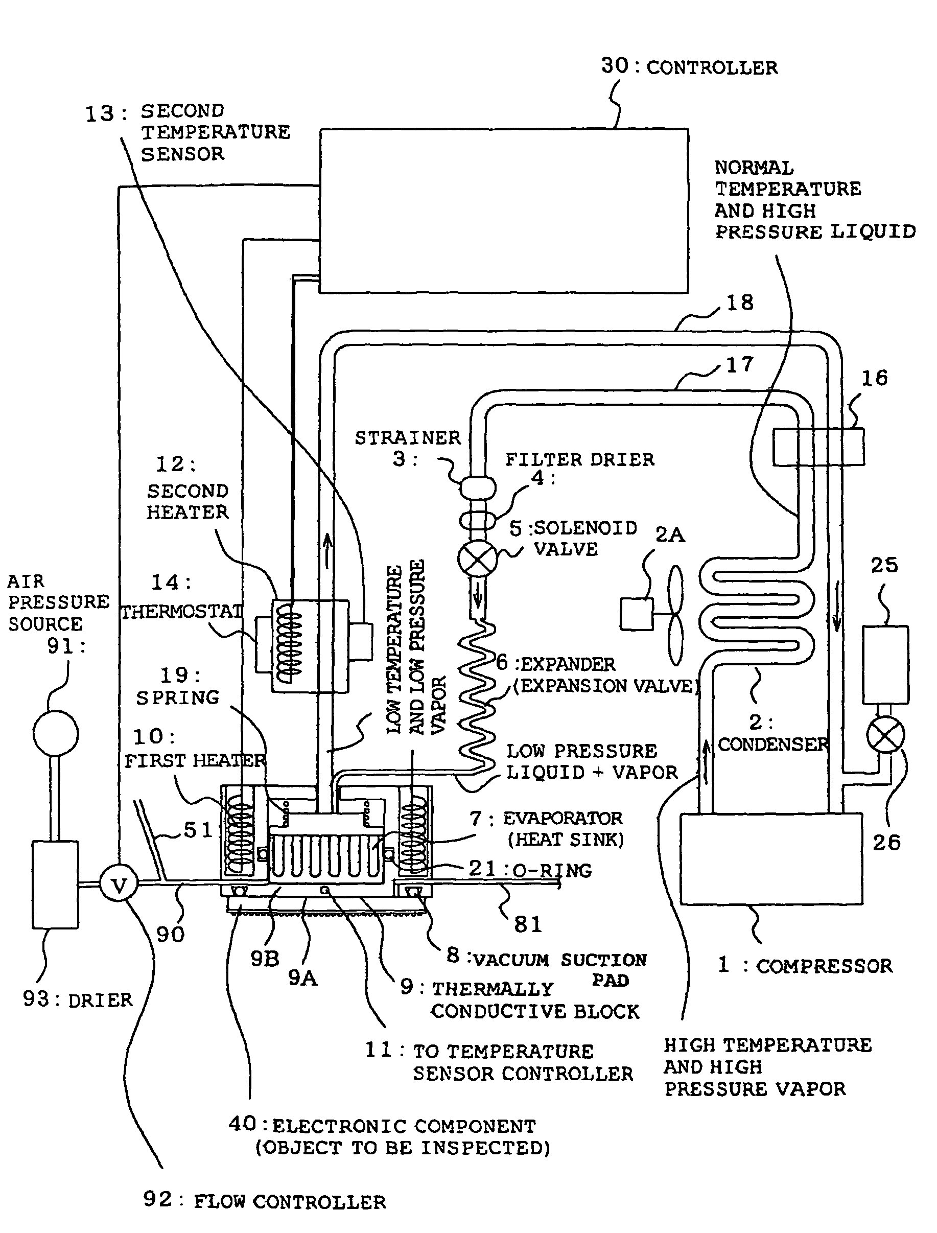
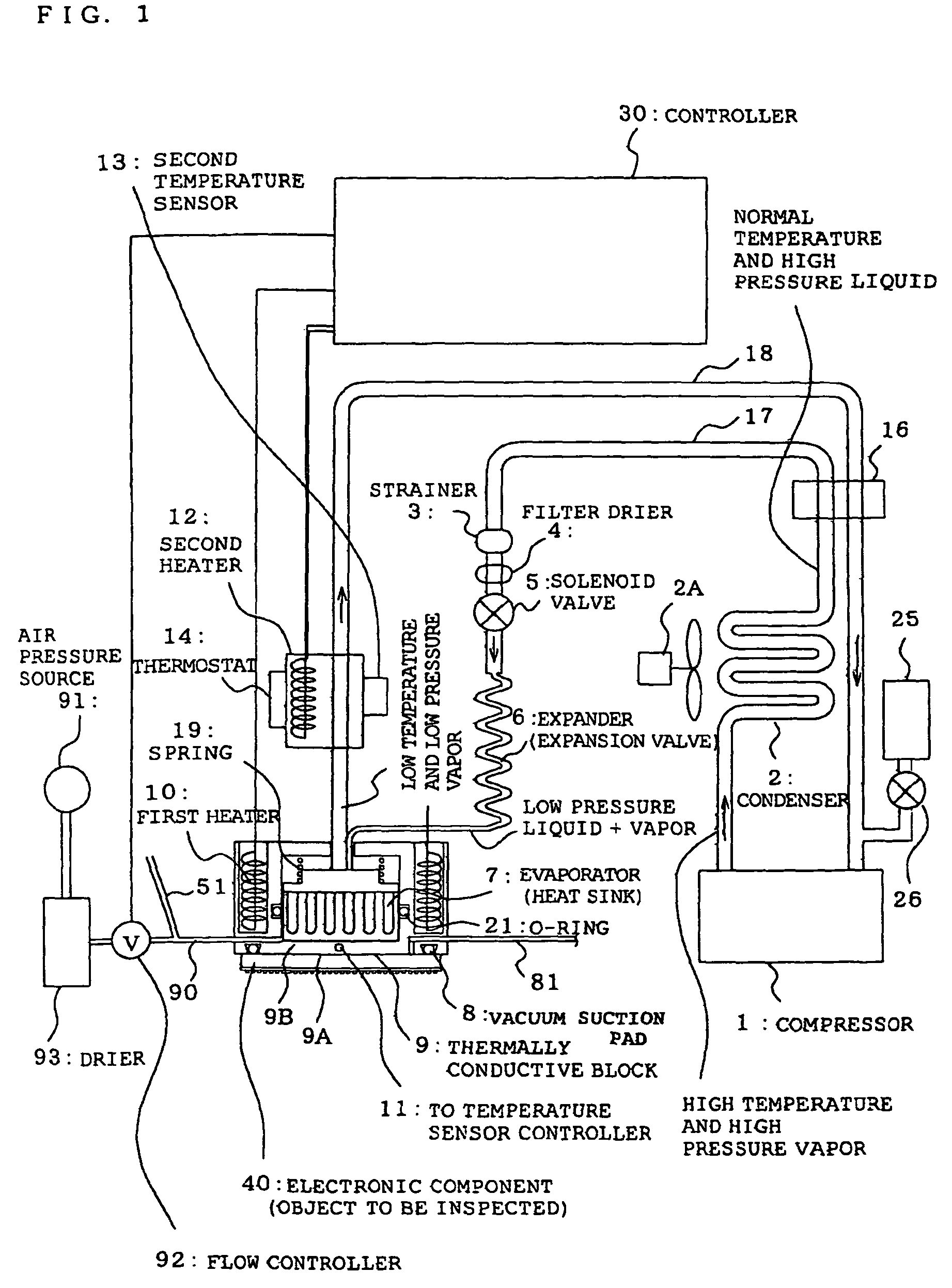
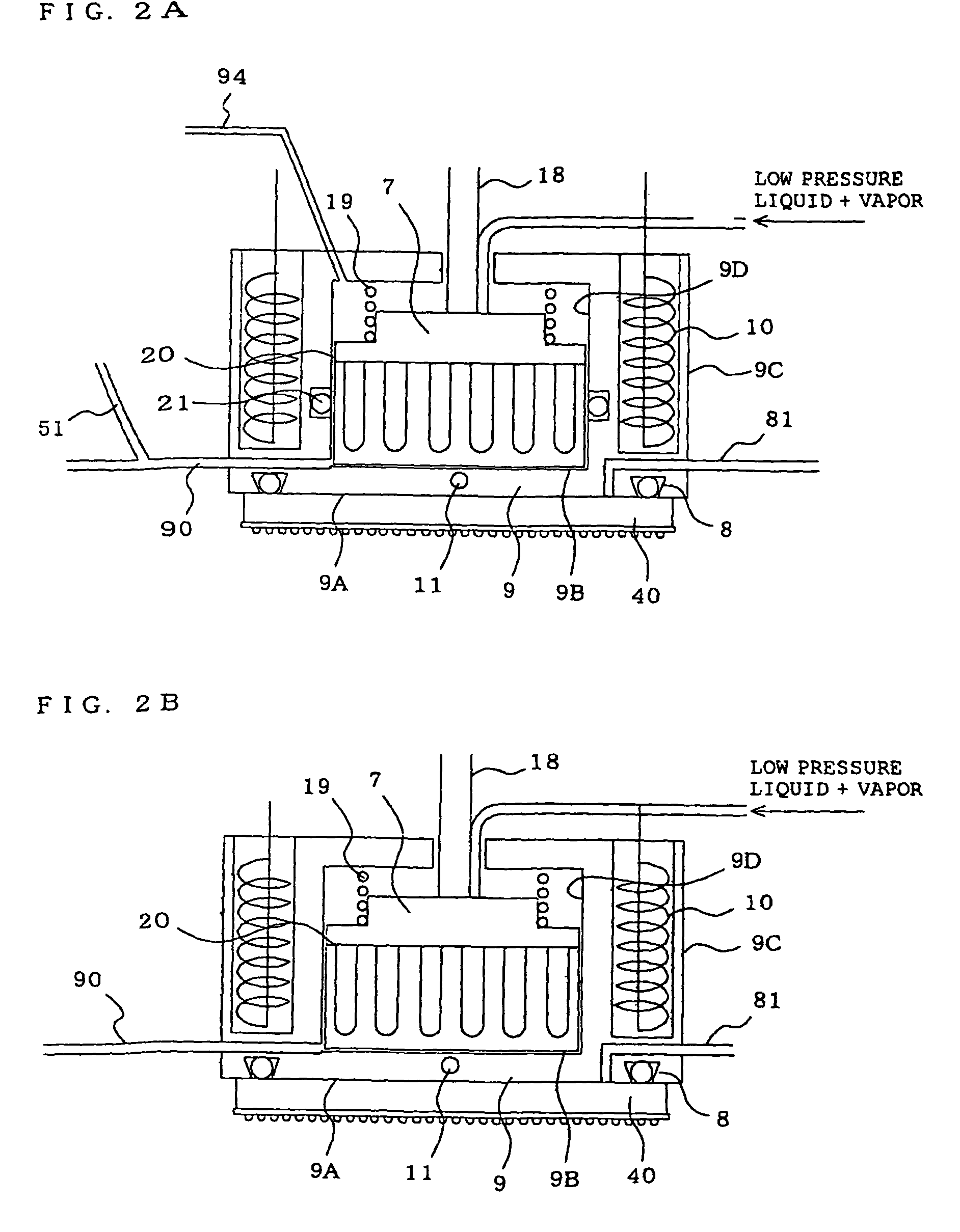
[0035]FIG. 1 is an entire schematic view of a temperature control unit for an electronic component according to a first embodiment of the present invention. Moreover, FIG. 2 is a sectional view of an electronic component cooling part (the below described part composed of an evaporator, a thermally conductive block, and suction pad, however, in some cases there is no suction pad) of the temperature control unit in FIG. 1. The main difference between FIG. 2A and FIG. 2B, is presence or non-presence of an o-ring between the evaporator and the thermally conductive block.

[0036]The temperature control unit includes a circulation circuit of a refrigerant where a compressor 1, condenser 2, an expander (for example, an expansion valve) 6, and an evaporator 7 are connected by pipes 17 and 18, and a cooling cycle system is configured by the refrigerant circulating circuit. Among those, the evaporator 7 is directly responsible for a temperature control of the electronic component 40 as a heat s...

second embodiment

[0063]FIG. 4 is a schematic view of a handler apparatus according to a second embodiment of the present invention. The handler apparatus is a handling apparatus for an electronic component, which can perform characteristic inspection of the electronic component by maintaining the electronic component (including a device) at a predetermined temperature, and pressing it to a tester that is a separated body from the handler apparatus. The handling apparatus, in order to temperature-control the electronic component to be inspected, includes the temperature control unit described in the first embodiment. In addition, symbols 1, 2, 17 and 18 designated in FIG. 4, correspond to the same symbols in the first embodiment. Moreover, a measuring hand 60A constituting a measuring robot part 60 represented in FIG. 4, corresponds to the electronic component cooling part of the first embodiment. Hereinafter, using an IC (not shown) as the electronic component to be inspected, an inspection process ...


PUM


Abstract

A temperature control unit for an electronic component and a handler apparatus, which are excellent in responsibility during cooling and heating, is obtained. The temperature control unit for an electronic component includes a cooling cycle device having a refrigerant passage circulating through a compressor, a condenser, an expander, and an evaporator; a thermally conductive block having an outer surface capable of coming in contact with the electronic component that is an object to be temperature-controlled, where an inner surface corresponding to the outer surface is placed opposite to the outer surface so as to be brought in contact with or apart from the evaporator; at least one first heater for heating the thermally conductive block; and a compressed air feeding circuit for feeding compressed air between facing surfaces of the evaporator and the thermally conductive block to part them.

Description

[0001]The entire disclosure of Japanese Patent Application No. 2005-261591, filed Sep. 9, 2005, is expressly incorporated by reference herein.BACKGROUND[0002]1. Field of the Invention[0003]The present invention relates to a temperature control unit for an electronic component which is used for characteristic inspection of the electronic component, and a handler apparatus including the temperature control unit.[0004]2. Description of the Related Art[0005]In characteristic inspection of the electronic component such as an IC, there is a temperature loading test where the electronic component is inspected while being maintained at a predetermined temperature. In the temperature loading test, it is required to inspect the electronic component under a correct temperature loading while compensating the temperature change due to self-heating of the electronic component. Especially, in recent years, as represented by a CPU of a personal computer, there is a tendency that as the electronic c...

Claims


Application Information

Patent Timeline
Patent Type & Authority Patents(United States)
IPC IPC(8): F25D23/12H01L23/34H05K7/20
CPCG06F1/20G06F1/206H01L23/34H01L2924/0002H01L2924/00G01R31/26H01L22/00
Inventor NAKAMURA, SATOSHI
Owner NS TECH INC
Learn More