
Valves

a valve and valve body technology, applied in the field of valves, can solve the problems of not being able to fully open the valve and the valve may not be fully opened

Inactive Publication Date: 2010-06-01
SMITHS GRP PLC
View PDF18 Cites 28 Cited by
  • Summary
  • Abstract
  • Description
  • Claims
  • Application Information

AI Technical Summary

Benefits of technology

[0010]The assembly may include a cleaning chamber located towards the patient end of the assembly, the valve being located towards the patient side of the cleaning chamber and the valve being openable to allow extension of the suction catheter and being closable substantially to isolate the cleaning chamber from the patient and enable cleaning of the catheter. Alternatively, the valve may be located towards the machine end of the assembly and be connected at the machine end of the suction catheter so as to enable or prevent suctioning along the catheter.

Problems solved by technology

This can be tiring in prolonged operation and means that the user has to occupy one hand maintaining the valve open.
There is also a risk that the valve may not be held fully open during extension of the catheter.
This could cause dragging on the catheter and may wipe secretions from the outside of the catheter in a position where they could move back into the airway.
Furthermore, there is a risk that twisting or bending the assembly in the region of the cleaning chamber could inadvertently open the valve.

Method used


Image

  • Valves
  • Valves
  • Valves

Examples


Embodiment Construction

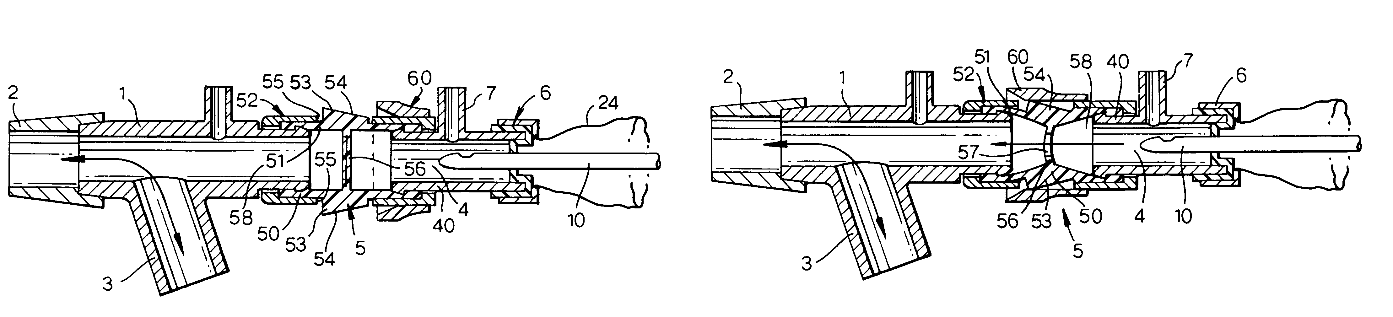
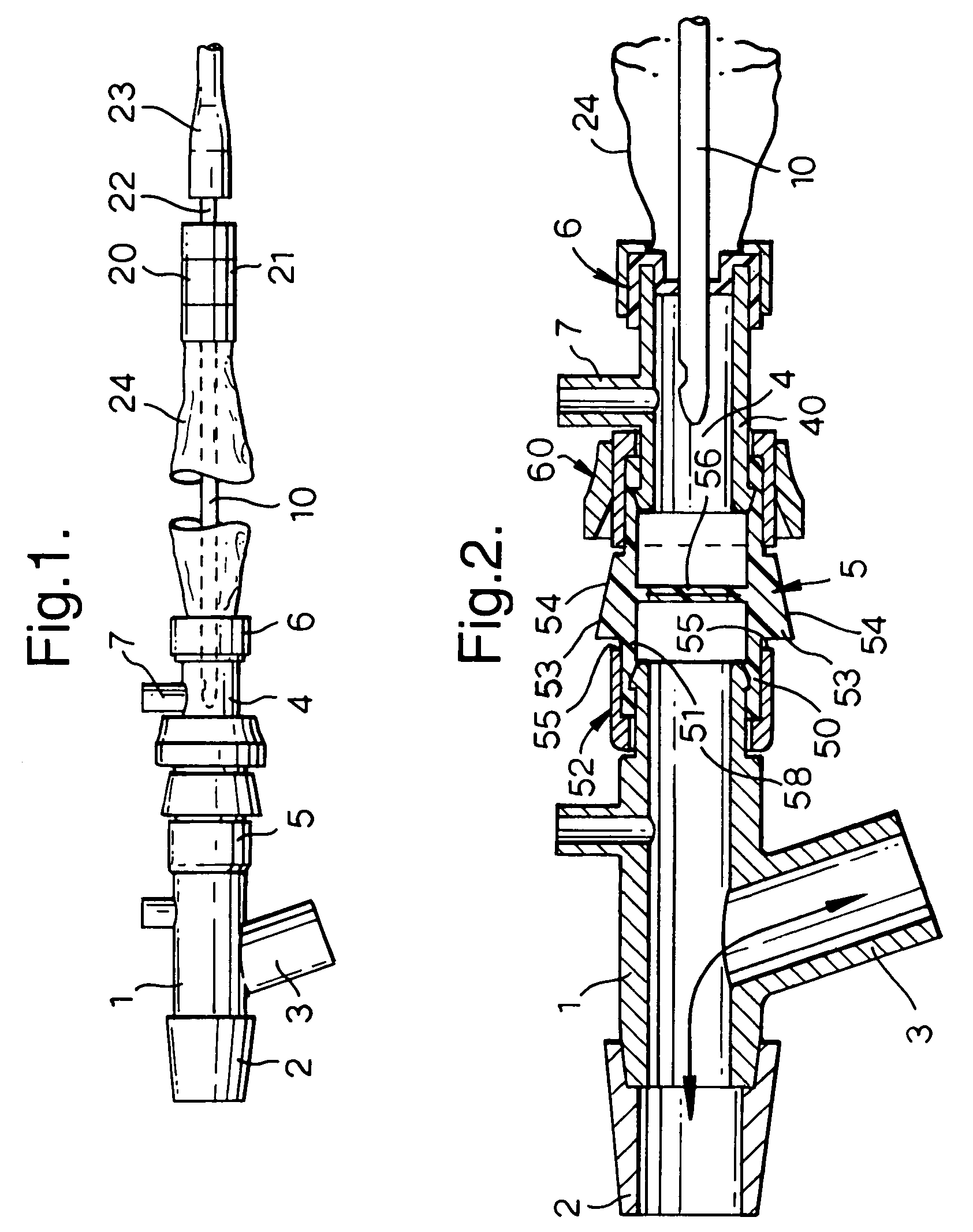
[0017]With reference first to FIG. 1, the assembly comprises a patient end fitting 1 having a tapered female coupling 2 at one end adapted to fit with a male connector on the end of a tracheal tube (not shown). The fitting 1 has a side coupling 3 adapted for connection to a ventilation system. Joined with the rear end of the fitting 1 is a cleaning chamber 4 having a valve 5 at its forward end and a wiper seal 6 at its rear end. An irrigation port 7 opens into the cleaning chamber 4. The forward end of a suction catheter 10 extends slidably through the wiper seal 6 and is located rearwardly of the valve 5, when not in use. The rear end of the suction catheter 10 is fixed at a machine end fitting 20, which includes a suction control valve 21 and a spigot 22 connected to flexible tubing 23 extending to a suction source (not shown). The valve 21 has a normally closed state, where no suction is applied to the catheter 10, but can be actuated manually to open it and apply suction from th...


PUM


Abstract

A closed system suction catheter has a catheter enclosed within a flexible envelope secured between a patient end fitting and a machine end fitting. The patient end fitting has a cleaning chamber with a valve at its patient side and is normally closed so that the cleaning chamber is isolated from the patient. The valve has an outer rigid housing enclosing a one-piece elastomeric moulding of tubular shape. The elastomeric moulding has two pads projecting externally through openings in the outer housing. The elastomeric moulding also has a web extending internally across its diameter with a diametrically-extending slit aligned with the pads. A collar mounted on the housing is slidable along the housing to engage the pads so as to apply pressure across the web and open the slit, thereby allowing the catheter to be advanced to the patient.

Description

BACKGROUND OF THE INVENTION[0001]This invention relates to valves.[0002]Closed system suction catheter assemblies are used for removing secretions from within the trachea or bronchii of an intubated patient. The assembly comprises a flexible catheter connected at its machine end with a fitting including a valve that can be opened or closed to control the application of suction to the catheter. The valve is usually of a kind having a valve member movable laterally of a flow path between two positions where flow is either enabled or prevented.[0003]Towards its patient end, the catheter extends through a forward, patient end fitting connected between the end of a tracheal tube and a ventilation circuit. The catheter can be advanced through the forward coupling down the tracheal tube to enable suctioning. A flexible envelope extends between the two couplings, enclosing the catheter so that it can be manipulated through the envelope. A wiper seal in the forward coupling prevents gas from...

Claims


Application Information

Patent Timeline
IPC IPC(8): A61M16/20A61M16/00A61M16/04A61M39/00A61M39/06F16K15/18F16K31/44
CPCA61M16/0463A61M39/0613F16K31/445F16K15/185A61M2039/0633A61M2039/062F16K15/1825
Inventor FIELD, STEPHEN JAMES
Owner SMITHS GRP PLC
Learn More