Automatic trip gate

a technology of automatic gate and trip gate, which is applied in water cleaning, water/sludge/sewage treatment, chemistry apparatus and processes, etc., can solve the problems of reducing the head or storage behind the dam, and affecting the operation of the trip ga

Inactive Publication Date: 2010-06-01
MCCREEDY C THOMAS +1
View PDF23 Cites 4 Cited by
  • Summary
  • Abstract
  • Description
  • Claims
  • Application Information

AI Technical Summary

Problems solved by technology

In the event that the bypass failed the canal would be over topped, and possibly wash out.
This, however, reduces head or storage behind the dam.

Method used


Image

  • Automatic trip gate
  • Automatic trip gate
  • Automatic trip gate

Examples


Embodiment Construction

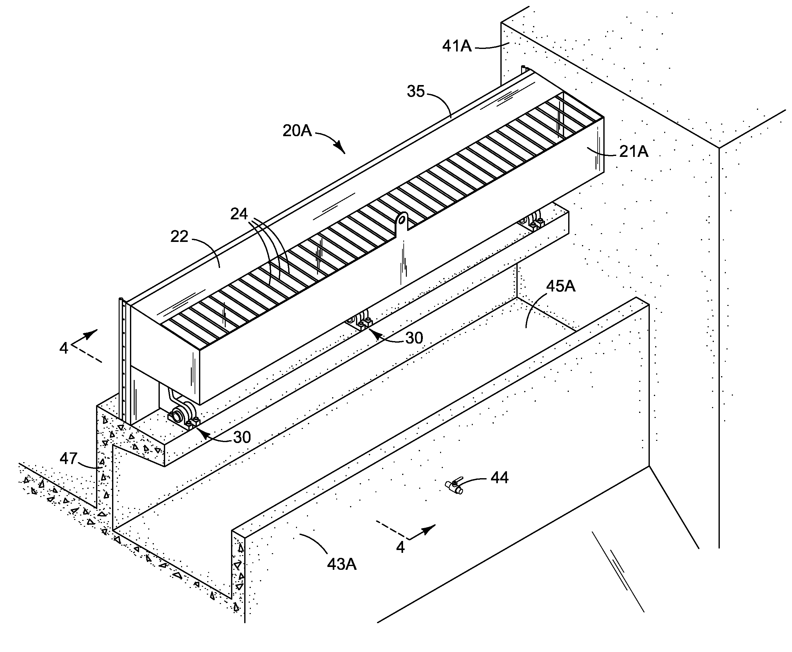
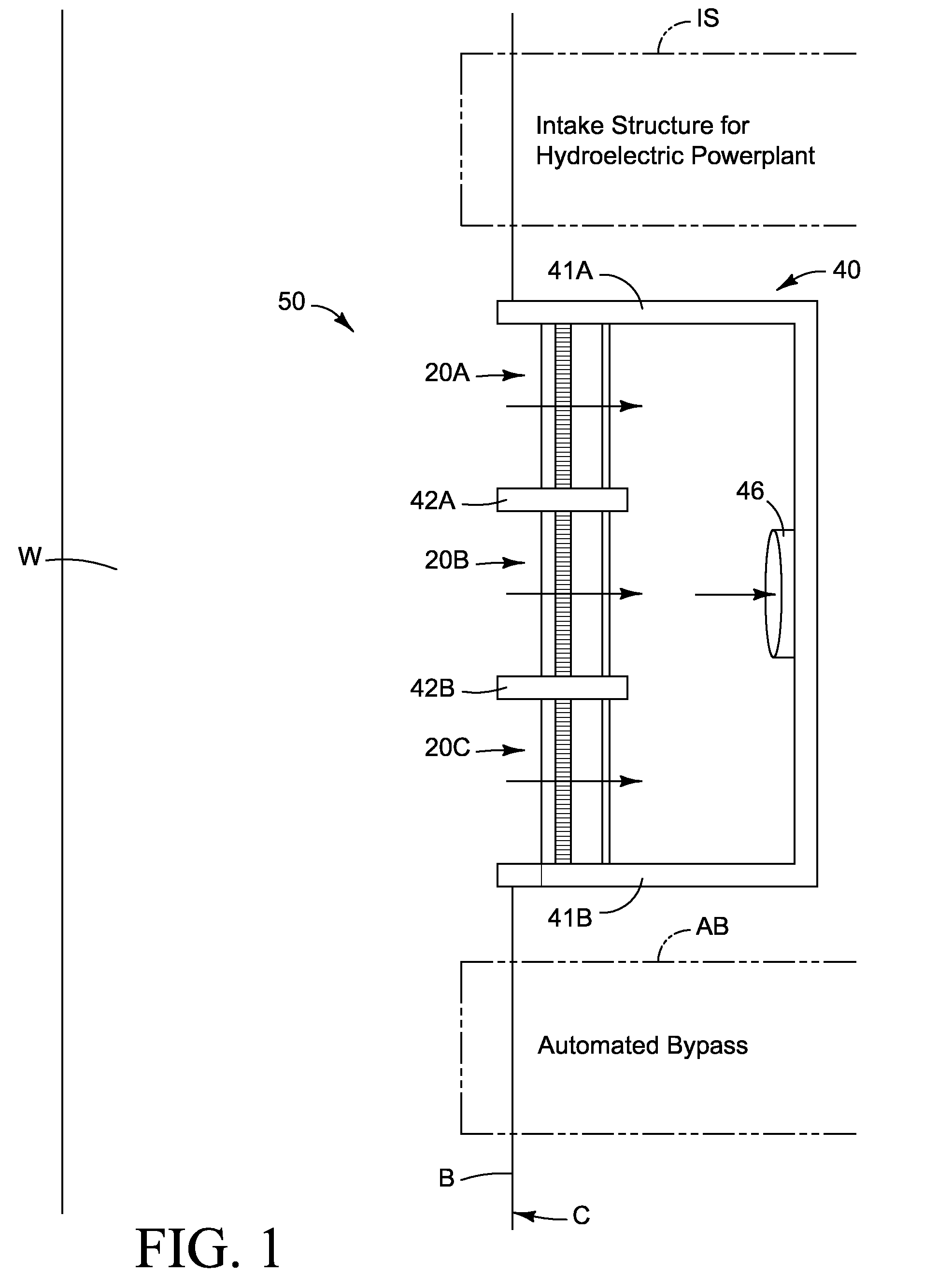
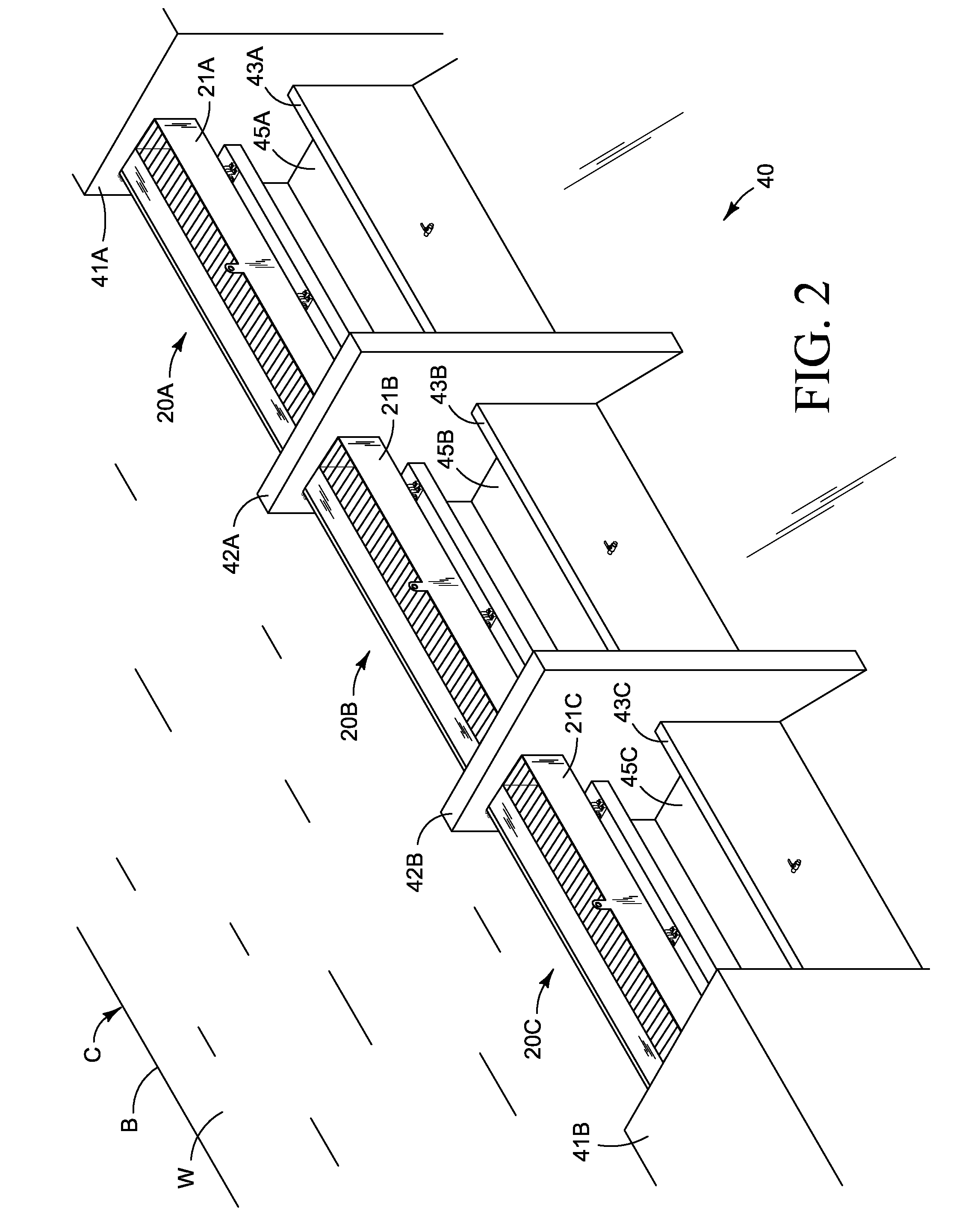
[0016]FIG. 1 a typical installation of automatic trip gate system 50 including in this installation three separate automatic trip gates 20A, 20B and 20C. In the instance represented in FIG. 1, automatic trip gate system 50 is installed at a location on canal C, where a low head hydroelectric plant, (not shown), has been established. Intake structure IS provides a flow of water to the hydro-electric plant during generation. When the hydroelectric plant experiences an unexpected shut down, overflow of canal water is handled by automated bypass AB, which is controlled in conjunction with the control of operation of the hydroelectric plant such that while water is flowing through the intake structure IS to the turbine, (not shown), located in the hydroelectric plant, a controlled valve, (not shown), of the automated bypass AB is closed so that flow is diverted through the intake structure IS. When the hydro-electric plant is out of service or operation, the controlled valve of the autom...


PUM


Abstract

An automatic trip gate for installation in a gate support structure at a bank of an impounded body of water. The automatic trip gate controls a release of an overflow of water through the gate support structure upon the occurrence of an overflow event. The automatic trip gate includes a plate supported by a hinge assembly that attaches to the support structure. A trough attached to the plate catches and retains overflow water. When the level of overflow water in the trough reaches a tipping level, the plate pivots from a substantially vertical orientation wherein the impounded body of water is maintained behind the plate, to a tipped position wherein the impounded body of water is released o through the gate support. A plunge pool is located below the automatic trip gate that absorbs the energy imparted by the plate when tripped.

Description

RELATED APPLICATIONS[0001]This application claims the priority of Provisional Application Ser. No. 60 / 821,990 entitled Spillway Weir Gate, filed Aug. 10, 2006, the content of said application being incorporated herein by reference.BACKGROUND OF THE INVENTION[0002]A device for diverting flow from a canal drop, small earthen dam or branch to an emergency spillway should a primary diversion fail unexpectedly was required at a small hydroelectric project being developed by the inventors. Several commercial products were available, such as the Obermeir Hydro, Inc. Pneumatically Operated Spillway Gate. This gate consists of a hinged plate held in place by an air bladder. In order to operate, this product includes a control valve, which could fail to operate. In the interest of providing a gate with no controls, a simple, economical alternative was required.SUMMARY OF THE INVENTION[0003]The present invention is directed to a device and method for directing or diverting a flow of water from...

Claims


Application Information

Patent Timeline
Patent Type & Authority Patents(United States)
IPC IPC(8): E02B7/40
CPCE02B7/16E02B8/06E02B7/40
Inventor MCCREEDY, C. THOMASDAUGHERTY, DENNIS
Owner MCCREEDY C THOMAS
Why Eureka
Try Eureka