Water amusement park water channel flow system

a technology of water channel flow and water amusement park, which is applied in the direction of acquatic toys, marine site engineering, construction, etc., can solve the problems of short duration of traditional downhill water rides, add to the cost of water park development, and high development cost of water parks

Inactive Publication Date: 2010-06-01
WATER RIDE CONCEPTS
View PDF454 Cites 35 Cited by
  • Summary
  • Abstract
  • Description
  • Claims
  • Application Information

AI Technical Summary

Benefits of technology

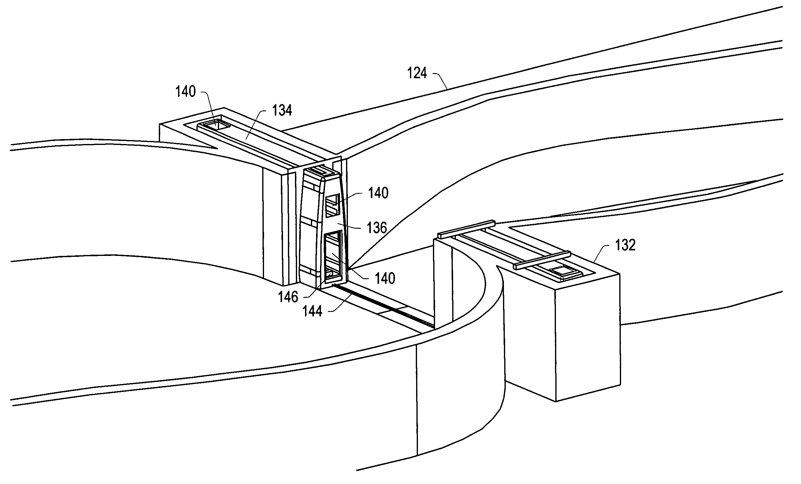
[0016]In certain embodiments, a restriction in a water channel limits the amount of water flowing in the water channel. An adjustable bypass channel (e.g., a jet gate) may be used to limit the amount of water flowing in the water channel (i.e., the adjustable bypass channel is the restriction). A portion of the flow of water in the water channel may be diverted into the adjustable bypass channel. Adjusting the amount of water exiting the adjustable bypass channel adjusts the amount of water flowing in the water channel past the adjustable bypass channel. Restricting the amount of water flowing in the water channel controls the hydraulic profile of the water flowing in the channel without physically altering the width of the water channel.
[0018]In an embodiment, an adjustable bypass channel includes a water entrance, a water exit, and an adjustable valve (e.g., a butterfly valve). The water entrance is in fluid communication with water upstream of the adjustable bypass channel. The water exit is in fluid communication with water downstream of the adjustable bypass channel. The flow rate of water exiting the adjustable bypass channel may increase from the flow rate of water upstream of the adjustable bypass channel (e.g., the water may flow through a restriction that increases the velocity (flow rate) of the water in the adjustable bypass channel). The adjustable valve is located between the water entrance and the water exit. The adjustable valve may be adjusted to control an amount of water exiting the adjustable bypass channel and / or a depth of water in the water channel upstream of the adjustable bypass channel. The adjustable bypass channel may increase the flow rate of water between the water entrance and the water exit of the adjustable bypass channel.

Problems solved by technology

With this phenomenal growth came the subsequent problem of finding enough appropriate land available for development into water recreation facilities.
One of the problems facing water park developers is finding enough land upon which to develop their water parks.
The development of water parks is an expensive enterprise to which the addition of having to purchase large tracts of land only further adds to the expense of developing water parks.
Generally speaking, the traditional downhill water rides are short in duration (normally measured in seconds of ride time) and have limited throughput capacity.
The combination of these two factors quickly leads to a situation in which patrons of the parks typically have long queue line waits of up to two or three hours for a ride that, although exciting, lasts only a few seconds.
Additional problems like hot and sunny weather, wet patrons, and other difficulties combine to create a very poor overall customer feeling of satisfaction or perceived entertainment value in the water park experience.
Poor entertainment value in water parks as well as other amusement parks is rated as the biggest problem of the water park industry and is substantially contributing to the failure of many water parks and threatens the entire industry.
Additionally, none of the typical downhill water park rides is specifically designed to transport guests between rides.
They are also generally unsuitable for water parks because of their high installation and operating costs and have poor ambience within the parks.
These types of transportation are also unsuitable for water park guests who, because of the large amount of time spent in the water, are often wet and want to be more active because of the combination of high ambient temperatures in summertime parks and the normal heat loss due to water immersion and evaporative cooling.
Mechanical transportation systems do not fit in well with these types of rides.
For water rides that involve the use of a floatation device (e.g., an inner tube or floating board) the walk back to the start of a ride may be particularly arduous since the rider must usually carry the floatation device from the exit of the ride back to the start of the ride.
Floatation devices could be transported from the exit to the entrance of the ride using mechanical transportation devices, but these devices are expensive to purchase and operate.
Carrying the floatation device or using mechanical transportation to transport the floatation device may reduce guest enjoyment, cause excess wear and tear on the floatation devices, contribute to guest injuries, and / or make it impossible for some guests to access the rides.
Also, a park that includes many different non-integrated rides may require guests to use different floatation devices for different rides, which makes it difficult for the park operators to provide the guests with a general purpose floatation device.
This leads to conditions of overcrowding in areas of the park which leads to guest dissatisfaction and general reduction of optimal guest dispersal throughout the park.
The lack of an efficient transportation system between rides accentuates this problem in water parks.
Sluice gates are typically unsuitable for use in water parks in which people participate due to safety reasons.
Adjustable submerged obstructions are generally expensive and difficult to install in a water park and / or are unsuitable for controlling the flow of water in a water park.
These moving parts may be unsuitable for water parks because of safety issues involving riders in the water channel, especially for the high volume flows of water seen in water parks.

Method used


Image

  • Water amusement park water channel flow system
  • Water amusement park water channel flow system
  • Water amusement park water channel flow system

Examples


Embodiment Construction

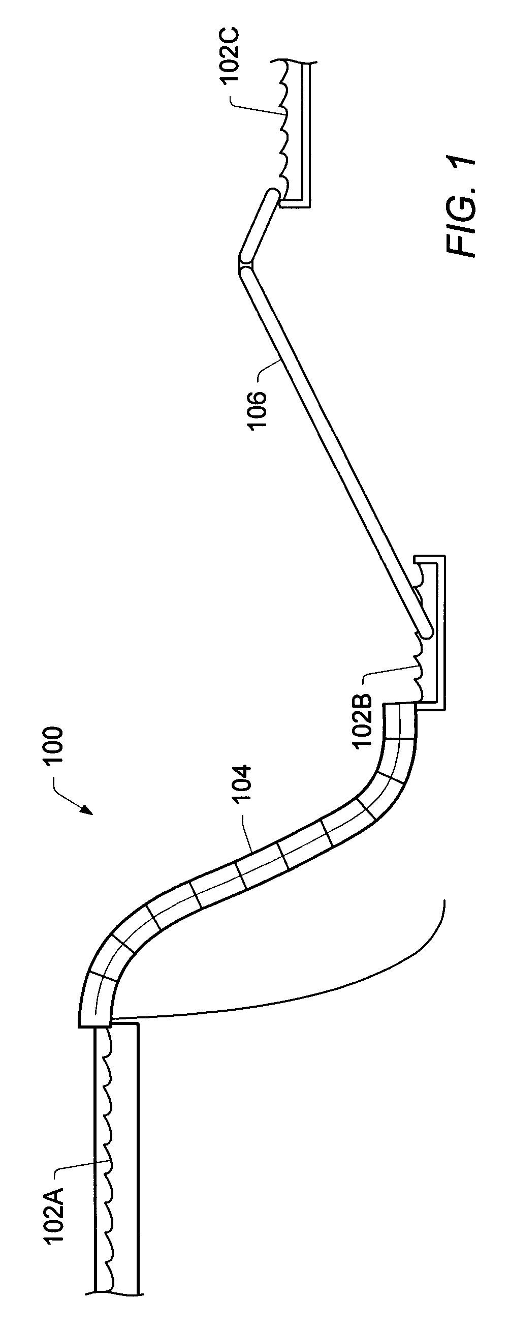
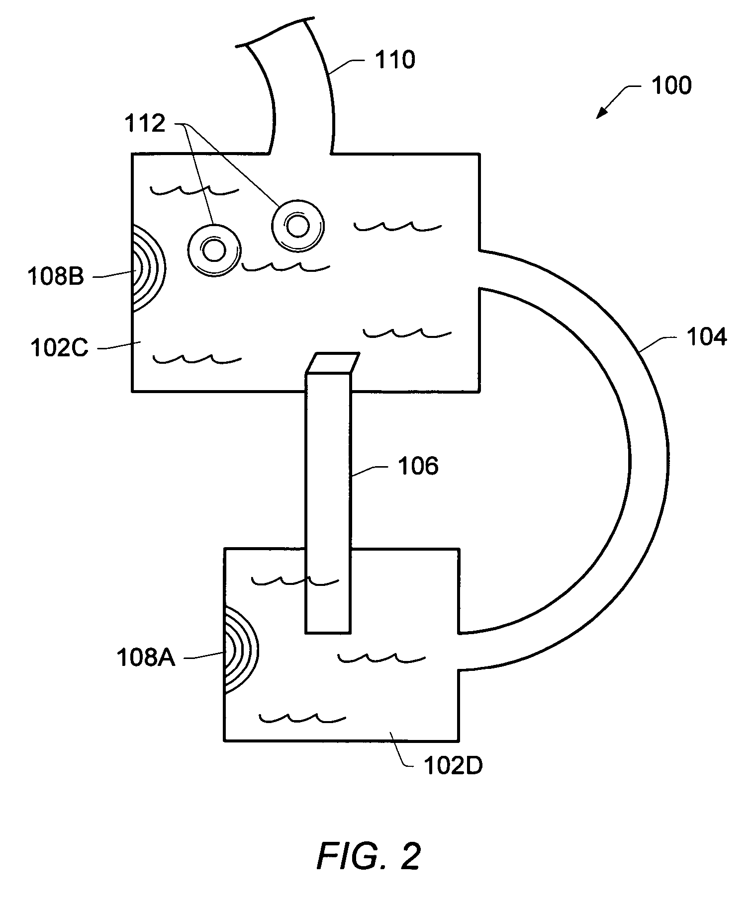
[0057]In some embodiments, a water amusement system (e.g., a water park) may include a “continuous water ride.” The continuous water ride may allow a participant using the continuous water ride to avoid long lines typically associated with many water amusement systems. Long lines and / or wait times are one of the greatest problems in the area of customer satisfaction associated with water amusement systems.

[0058]Almost all water park rides require substantial waiting periods in a queue line due to the large number of participants at the park. This waiting period is typically incorporated into the walk from the bottom of the ride back to the top, and can measure hours in length, while the ride itself lasts a few short minutes, if not less than a minute. A series of corrals are typically used to form a meandering line of participants that extends from the starting point of the ride toward the exit point of the ride. Besides the negative and time-consuming experience of waiting in line,...


PUM


Abstract

A water amusement ride system is disclosed. The system may include a device or apparatus, including a water bypass channel in fluid communication with a channel of water. The water bypass channel may include a water entrance, a water exit, and an adjustable valve. The water entrance is in fluid communication with water upstream of the apparatus. The water exit is in fluid communication with water downstream of the apparatus. The adjustable valve may be located between the water entrance and the water exit. The adjustable valve may be adjusted to control an amount of water exiting the water bypass channel. The water bypass channel may increase the flow rate of water between the water entrance and the water exit of the water bypass channel. The water bypass channel may assist in controlling a water effect.

Description

PRIORITY CLAIM[0001]This patent application claims priority to U.S. Provisional Patent Application Ser. No. 60 / 705,298 entitled “JET AND SIDE CONTROL GATES” filed on Aug. 3, 2005, and to U.S. Provisional Patent Application Ser. No. 60 / 717,568 entitled “WATER AMUSEMENT PARK WATER BYPASS CHANNEL AND CHANNEL FLOW ADJUSTMENT SYSTEM” filed on Sep. 15, 2005, the disclosures of which are hereby incorporated by reference.BACKGROUND[0002]1. Field of the Invention[0003]The present disclosure generally relates to water amusement attractions and rides. More particularly, the disclosure generally relates to jet and side control gates for controlling water flow in water amusement rides.[0004]2. Description of the Relevant Art[0005]The 80's decade witnessed phenomenal growth in the participatory family water recreation facility (i.e., the water park) and in water oriented ride attractions in the traditional themed amusement parks. The main current genre of water ride attractions (e.g., waterslides...

Claims


Application Information

Patent Timeline
Patent Type & Authority Patents(United States)
IPC IPC(8): A63G21/18A63G21/00
CPCA63G3/00A63G21/18
Inventor HENRY, JEFFERY WAYNESCHOOLEY, JOHN TIMOTHY
Owner WATER RIDE CONCEPTS
Why Eureka
Try Eureka