Method of a signal transmission for controlling a quantity of data transmitted and a signal transmission apparatus therefor

a technology of data transmission and signal transmission, which is applied in the field of method of signal transmission and signal transmission apparatus, can solve problems such as the problem of digital transmission of signals deteriorating

Inactive Publication Date: 2010-06-01
KOKUSA ELECTRIC CO LTD
View PDF12 Cites 66 Cited by
  • Summary
  • Abstract
  • Description
  • Claims
  • Application Information

AI Technical Summary

Benefits of technology

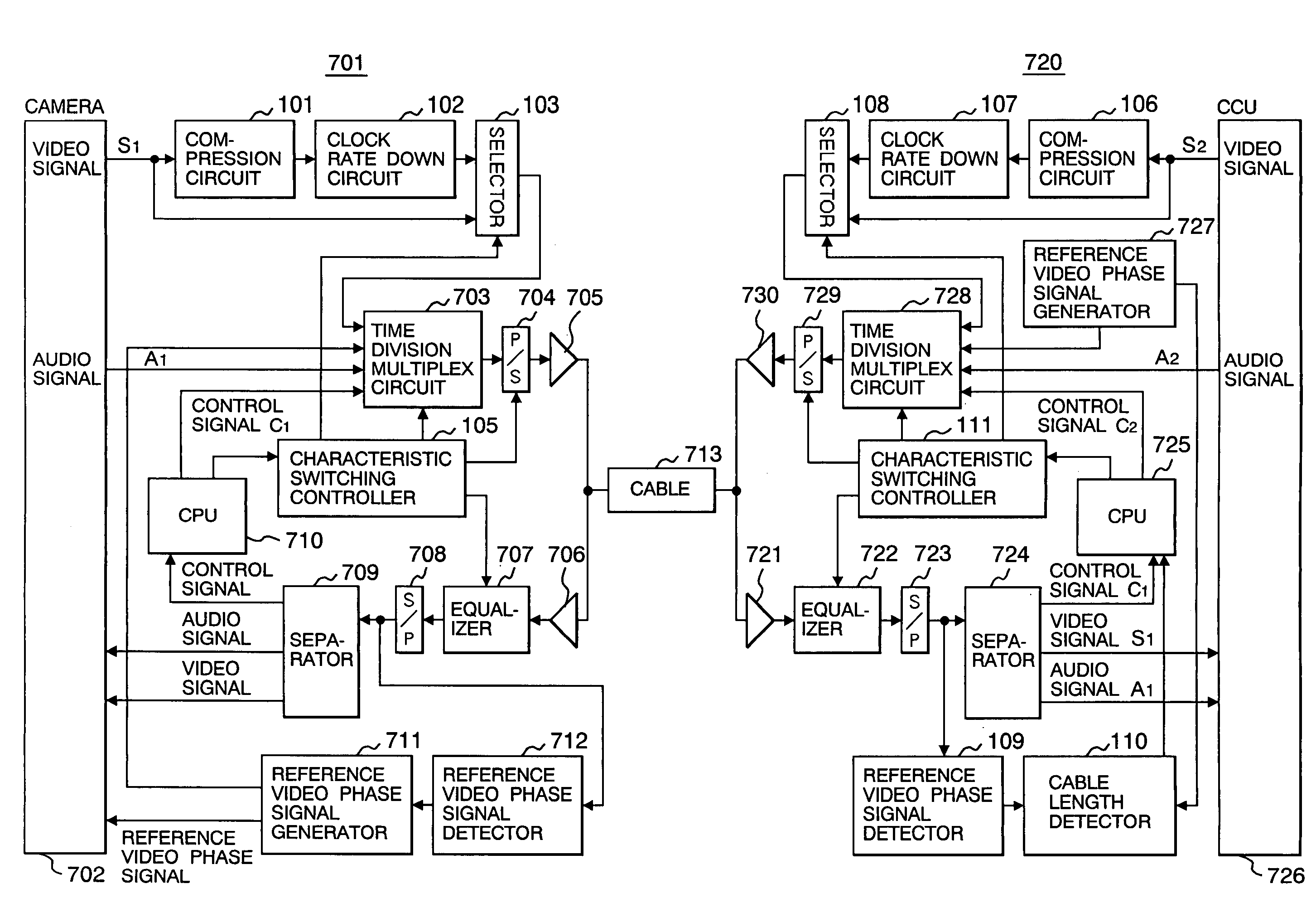
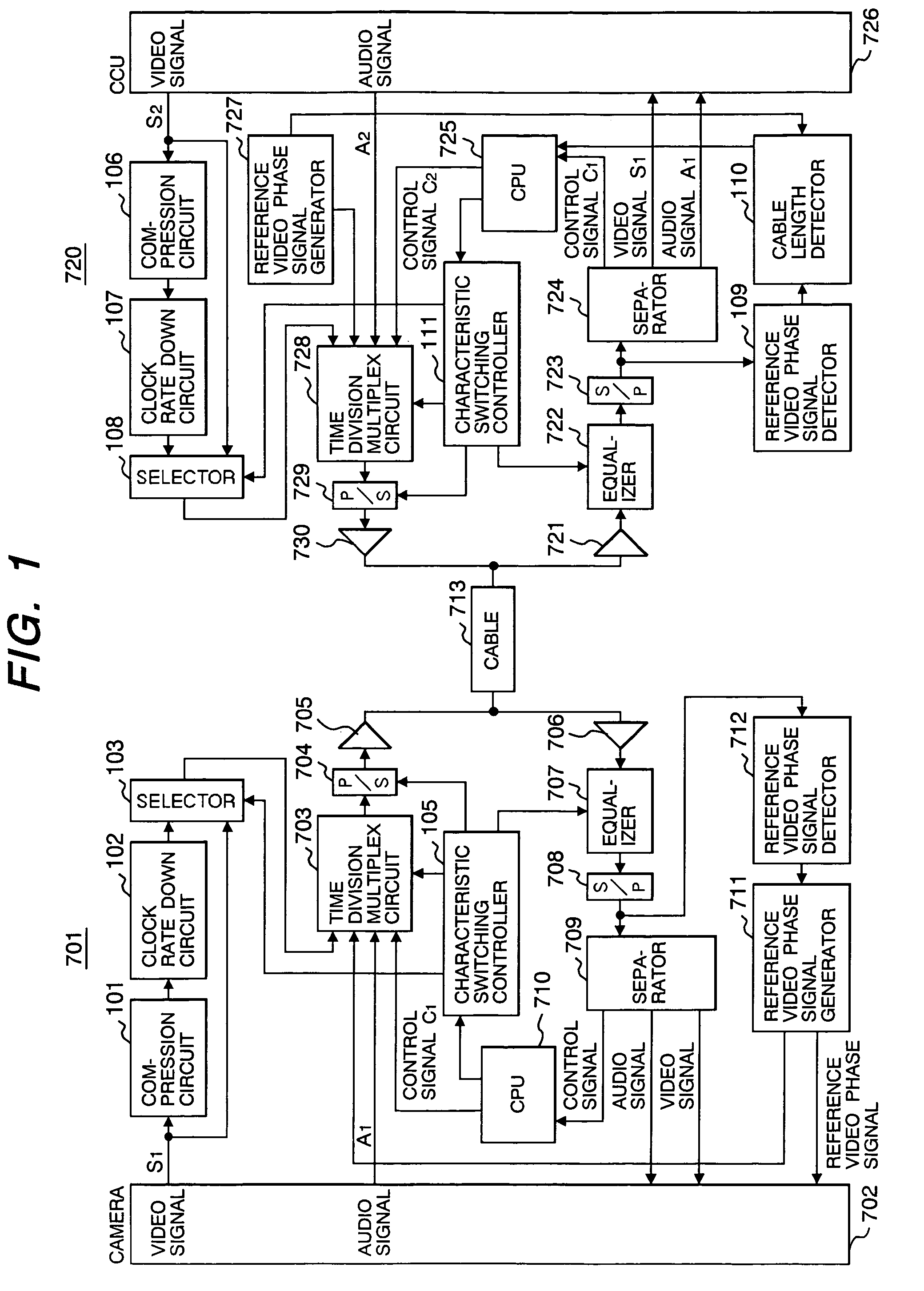
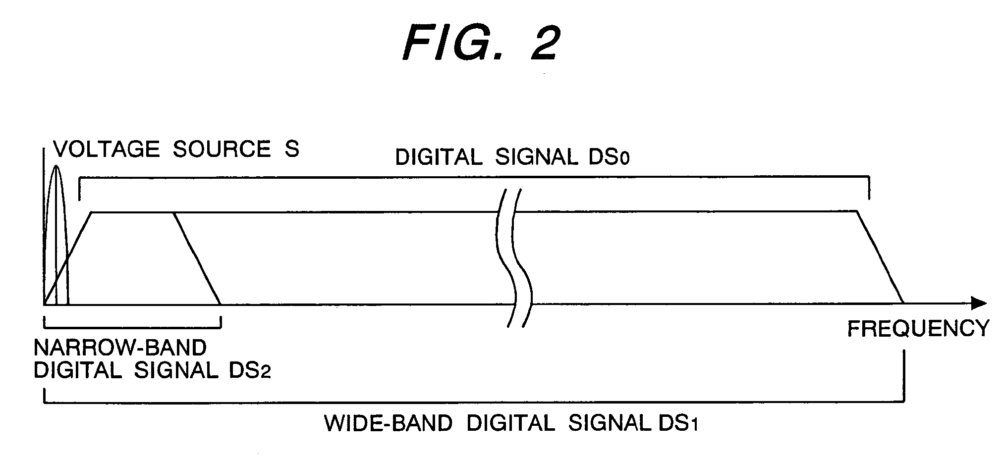
[0020]According to the present invention, there is also provided another version of the method of signal transmission stated above wherein the step of controlling on the basis of the measured value of delay the data quantity of signals delivered to the transmission path by at least one of the camera unit and the camera control unit comprises a step of reducing the data quantity of signals to be delivered to the transmission path and a step of switching over the frequency band required for the transmission.
[0025]According to the present invention, there is also provided still another version of the signal transmission apparatus described above wherein each of the camera unit and the camera control unit has an equalizer which compensates for the value of attenuation of the signals transmitted over the transmission path, and the value of compensation of the attenuation by the equalizer is controlled on the basis of the output signal of the data quantity controlling unit.

Problems solved by technology

However, when they are used outdoors, often for telecasting a baseball game or a golf tournament, the required distance between the camera unit and the camera control unit is 1 km or more, posing a deterioration problem to the digital transmission of signals.

Method used


Image

  • Method of a signal transmission for controlling a quantity of data transmitted and a signal transmission apparatus therefor
  • Method of a signal transmission for controlling a quantity of data transmitted and a signal transmission apparatus therefor
  • Method of a signal transmission for controlling a quantity of data transmitted and a signal transmission apparatus therefor

Examples


Embodiment Construction

[0035]According to the present invention, it is possible even for D1 signals to be reduced in data quantity to 1 / 10 or even less by using data compression based on high-efficiency coding. A reduction in data quantity further enables the clock rate of transmission to be reduced and the frequency band of transmission to be narrowed. If, for instance, 360 Mbps signals are compressed to 36 Mbps signals, the maximum cable length permitting transmission will be extended to around 1.5 km as indicated by Equation (2), and users' pertinent needs can be satisfied. In this case, however, video quality will be deteriorated by the data compression. There would arise the kinds of noise generally known as block noise and mosquito noise. These kinds of noise occur irrespective of the cable length, even where the cable length is short. Therefore, this is a disadvantage in a studio environment.

[0036]According to the present invention, there is provided means of reducing the data quantity by data comp...


PUM


Abstract

When digital signals are to be transmitted between a camera unit and a camera control unit, the distance of their transmission depends on the frequency at which the digital signals are transmitted. The higher the frequency of the digital signals is, the greater the cable attenuation is, inviting deterioration of the signals. Therefore, with a view to matching the quantity of transmitted signals with the length of the transmission path and thereby achieving high quality of signal transmission, a method of signal transmission for a signal transmission apparatus wherein a camera unit and a camera control unit for controlling the camera unit are connected by a transmission path and a video signal, an audio signal and a control signal are digitized, time division multiplexed and transmitted between the camera unit and the camera control unit, has a step of measuring the value of delay of signals transmitted over the transmission path, and each of the camera unit and the camera control unit performs a step of controlling the data quantity of signals to be delivered to the transmission path on the basis of the measured value of delay.

Description

FIELD OF THE INVENTION[0001]This invention relates to the field of a method of a signal transmission and a signal transmission apparatus, and more particularly to a method of a signal transmission for multiplex bidirectional transmission of a video, an audio and a control signals and the like between two video apparatuses and a signal transmission apparatus therefor.BACKGROUND OF THE INVENTION[0002]For use in multiplex transmission of data including a video signal, an audio signal and a control signal between video apparatuses such as a television camera (hereinafter referred to as camera unit) and a camera control apparatus (hereinafter referred to as camera control unit), there is known an apparatus which subjects data including the video signal, the audio signal and the control signal to frequency division multiplexing and transmits the multiplexed signals over a triple coaxial cable known as a Triax cable (hereinafter referred to as transmission cable).[0003]In Triax transmissio...

Claims


Application Information

Patent Timeline
Patent Type & Authority Patents(United States)
IPC IPC(8): H04L1/00H04B7/212H04L12/26H04L5/14H04J3/00H04N19/102H04L5/22H04N5/232H04N7/08H04N7/081H04N7/10H04N7/24H04N19/00H04N19/115H04N19/166H04N19/196H04N19/86
CPCH04N5/23203H04N23/66
Inventor TANABE, KAZUHIRO
Owner KOKUSA ELECTRIC CO LTD
Why Eureka
Try Eureka