Optical navigation apparatus using fixed beacons and a centroid sensing device

a technology of optical navigation and centroid sensing, applied in static indicating devices, instruments, angle measurement, etc., can solve the problems of low-cost and low-bandwidth applications, too resource-intensive approaches using markers on objects and cameras in the environment to recover object positions, and inability to accurately determine the position of objects

Inactive Publication Date: 2010-06-01
ELECTRONICS SCRIPTING PRODS
View PDF32 Cites 160 Cited by
  • Summary
  • Abstract
  • Description
  • Claims
  • Application Information

AI Technical Summary

Benefits of technology

[0019]In some embodiments it is advantageous to amplitude modulate the beacons at predetermined frequencies. This may be done for improving filtering and signal detection in an otherwise optically noisy environment, e.g., outdoors. The on / off timing of the sequenced pattern can include one or more beacons lighting up or emitting at one time.

Problems solved by technology

In general, motion capture tends to be computationally expensive because of significant image pre-and post-processing requirements, as well as additional computation associated with segmentation and implementation of algorithms.
The above approaches using markers on objects and cameras in the environment to recover object position, orientation or trajectory are still too resource-intensive for low-cost and low-bandwidth applications.
This is due to the large bandwidth needed to transmit image data captured by cameras, the computational cost to the host computer associated with processing image data, and the data network complexity due to the spatially complicated distribution of equipment (i.e., placement and coordination of several cameras in the environment with the central processing unit and overall system synchronization).
The use of PSDs in optical motion capture and navigation systems brings many advantages, but is not sufficiently agile for applications involving high-precision, low-bandwidth and high capture rate navigation of small objects.
In addition, the systems are ill-suited in situations where the objects are hand-held because the requirement for positioning cameras in the user's environment (e.g., working area) is constraining.
For example, when navigating a hand-held object such as a mouse or a jotting implement, e.g., as described in U.S. Pat. No. 7,203,384 to Carl, the distributed nature of a motion capture system in a jotting environment even if employing PSD sensors is cumbersome.

Method used


Image

  • Optical navigation apparatus using fixed beacons and a centroid sensing device
  • Optical navigation apparatus using fixed beacons and a centroid sensing device
  • Optical navigation apparatus using fixed beacons and a centroid sensing device

Examples


Embodiment Construction

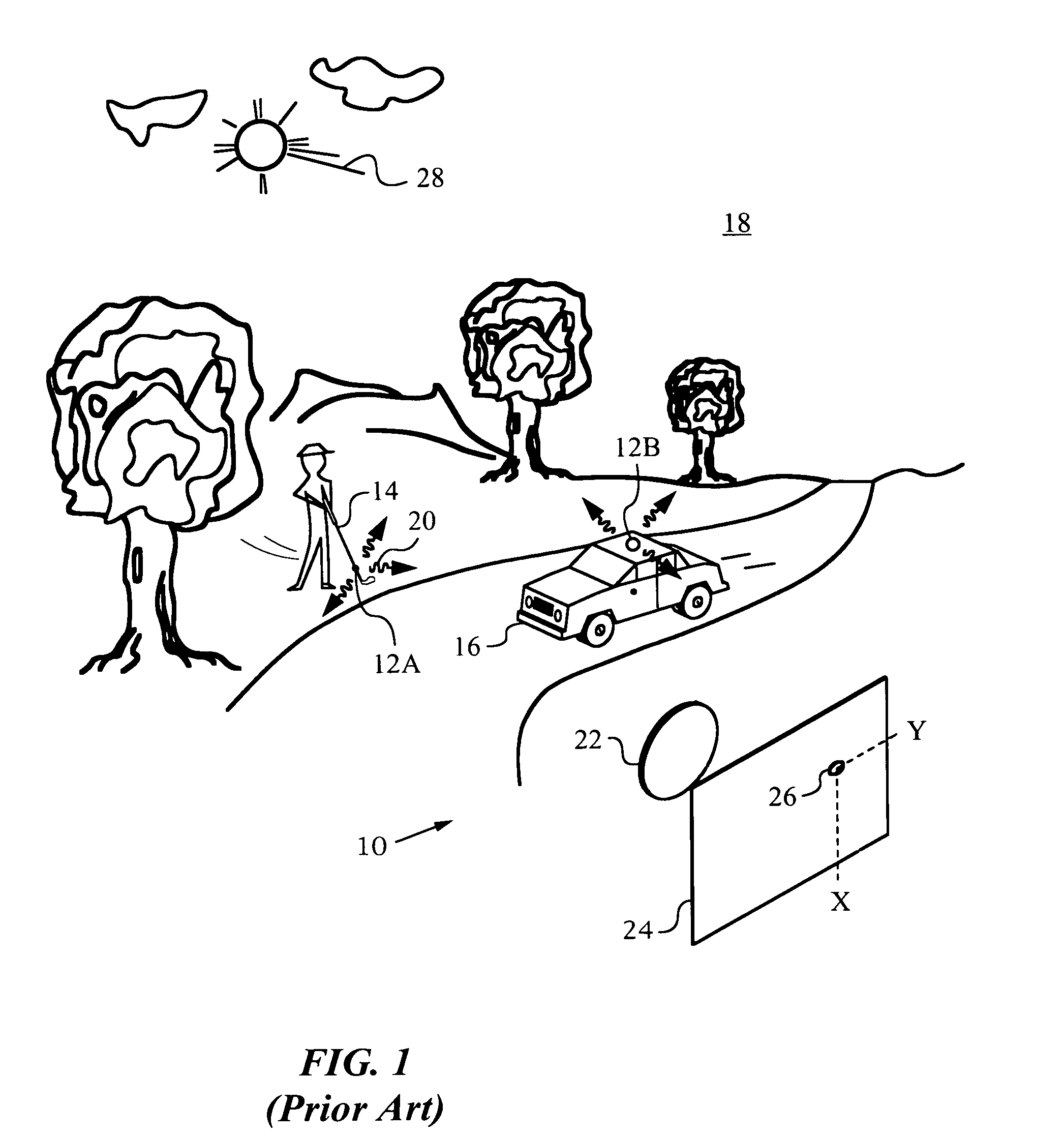
[0048]The many novel and unobvious aspects of the present invention will be best understood by initially referring to a prior art system 10 as shown in FIG. 1. System 10 is a distributed motion capture system employing illuminated markers 12A, 12B attached to objects 14, 16 that are tracked in an environment 18. Markers 12A, 12B emit electromagnetic radiation 20 of a certain wavelength at known times. An optic 22 images radiation 20 on a position sensitive detector (PSD) 24 placed at a known location in environment 18. Note that most prior art motion capture systems use several detector modules to achieve a large field of view and higher measurement accuracy.

[0049]PSD 24 measures the center-of-mass or centroid 26 of the imaged radiation 20, which is typically the center of a spot corresponding to the marker that is active at the time of measurement. In other words, PSD 24 provides an x and a y position in its sensor plane corresponding to the centroid of the intensity distribution c...


PUM


Abstract

The present invention relates to an optical navigation system for determining a pose, which includes the position and orientation of an object in an environment. The optical navigation system uses a number of beacons affixed at known locations in the environment to provide electromagnetic radiation in a sequenced pattern. An on-board optic images the radiation from the beacons onto an on-board centroid sensing device to obtain an imaged distribution of the radiation on the on-board centroid sensing device. The centroid sensing device determines the centroid of the imaged distribution and provides centroid information to a navigation unit for determining the pose of the object from the centroid. The navigation system is particularly well-suited for navigating hand-held objects.

Description

RELATED APPLICATIONS[0001]This application claims priority to U.S. Provisional Patent Application No. 60 / 780,937 filed on Mar. 8, 2006, which is incorporated herein in its entirety. This application is related to U.S. Pat. No. 7,474,809 filed on Mar. 26, 2007, which is a continuation-in-part of U.S. Pat. No. 7,203,384 filed on Aug. 13, 2003, which claims priority from U.S. Provisional Application No. 60 / 450,244 filed on Feb. 24, 2003.FIELD OF THE INVENTION[0002]The present invention relates generally to optical navigation of objects with the aid of fixed beacons for emitting electromagnetic radiation in a sequenced pattern and an on-board centroid sensing device.BACKGROUND OF THE INVENTION[0003]Optical navigation is an intuitive and precise way to track moving objects. The approach is intuitive because our own human stereo vision system calculates object locations and trajectories by optical triangulation. The precision of optical navigation is due to the very short wavelength of el...

Claims


Application Information

Patent Timeline
Patent Type & Authority Patents(United States)
IPC IPC(8): G06K9/00G06F3/033
CPCG06F3/0325G06F3/03545G06T7/0042G06F3/0425G06F3/0428G06F3/0423G06T7/73
Inventor MANDELLA, MICHAEL J.GONZALEZ-BANOS, HECTOR H.HAWKS, TIMOTHY J.ALBOSZTA, MAREK
Owner ELECTRONICS SCRIPTING PRODS
Why Eureka
Try Eureka