Power tool and overload protection

a technology of overload protection and power tools, applied in the field of power tools, can solve problems such as excessive heat of motors, and achieve the effect of maximum power

Inactive Publication Date: 2010-06-08
ROBERT BOSCH GMBH
View PDF10 Cites 8 Cited by
  • Summary
  • Abstract
  • Description
  • Claims
  • Application Information

AI Technical Summary

Benefits of technology

[0004]With an inventive power tool that includes a gear-shifting mechanism with a plurality of gears for selecting the power stages of a drive as needed, it is possible to couple an overload protection function with the gears. At least one gear is provided in which the overload protection function may be forcibly deactivated. With an inventive overload protection device, at least one gear is provided with a shut-off function that is forcibly deactivated when overload occurs. By coupling the gear-shift lever with electronics, maximum power is advantageously provided without the power tool being shut off prematurely by the overload protection function and without the power tool becoming overheated.
[0005]Favorably, the operator may select the power he requires for the particular application. A gear-shifting lever—preferably a rotary knob—is advantageously provided. The operator may select, e.g., a first gear with a higher reduction, as usual, when it is likely that strong loads will be placed on the power tool, e.g., due to high contact forces and torques. If less of a load will be placed on the power tool, the operator may select a second gear with a lower reduction. The electronics are designed such that the power tool shuts off automatically at a certain power level to prevent damage, to the electric motor and the transmission in particular. If greater power is still required, a third level may be selected. In this position—according to the present invention—the first gear with the lowest power stage is the mechanical default, with the overload protection function being shut off via the electronics. Advantageously, maximum possible output of the power tool is therefore available. With this coupling, it is possible to prevent the operator from operating in second gear, which would cause the motor to heat up too quickly.

Problems solved by technology

With this coupling, it is possible to prevent the operator from operating in second gear, which would cause the motor to heat up too quickly.

Method used


Image

  • Power tool and overload protection
  • Power tool and overload protection

Examples


Embodiment Construction

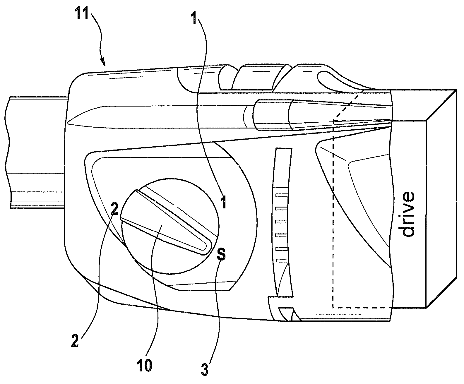
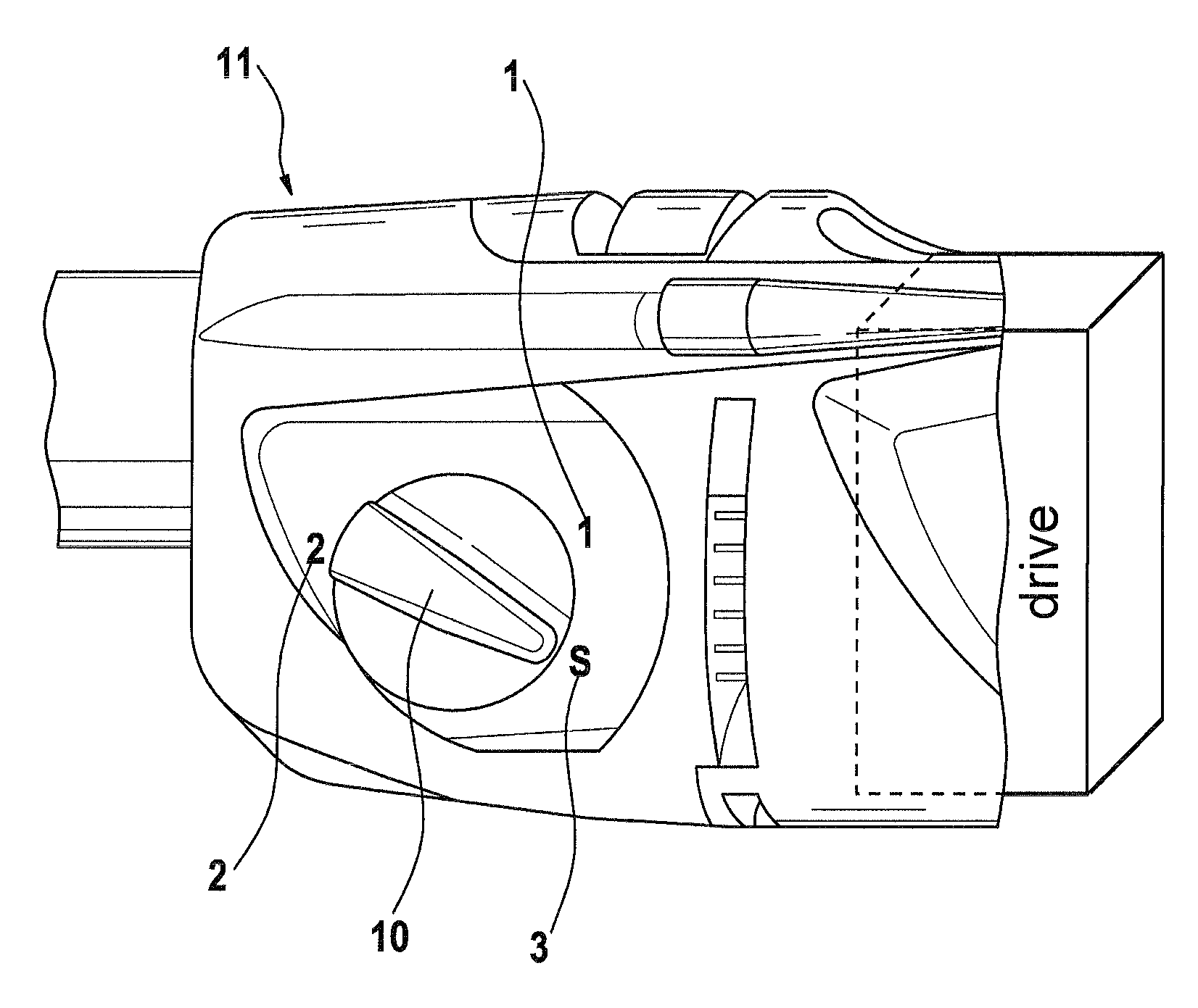
[0008]The sole FIGURE shows a detailed view of an embodiment of an inventive power tool 11, in which a rotary knob 10 is shown. Using rotary knob 10, a gear-shifting mechanism that includes a plurality of gears 1, 2 may be actuated for selecting power stages of a drive as required. Rotary knob 10 may be used to shift a mechanical transmission as usual. Using gear 1 and gear 2, it is possible to select between a higher reduction and a lower reduction. The electronics in gears 1 and 2 are designed such that power tool 11 shuts off automatically when a certain level of output is reached. The overload protection function is therefore active in gears 1 and 2.

[0009]If even greater power is desired, a gear 3 may be selected using rotary knob 10. Gear 1, with the lowest power stage, is the mechanical default, but the overload protection function may be forcibly deactivated. The maximum power that power tool 11 is capable of outputting may therefore be attained. At the same time, it is possi...


PUM


Abstract

The invention relates to a power tool having a change-speed gear device comprising a plurality of gears (1, 2) for adjusting on demand power stages of a drive, wherein an overload protection can be coupled to the gears (1, 2). According to the invention, the device comprises at least one gear (3) in which the overload protection function can be forcibly deactivated. The invention also relates to an overload protection.

Description

CROSS-REFERENCE TO RELATED APPLICATION[0001]The invention described and claimed hereinbelow is also described in German Patent Application DE 10 2005 037 254.6 filed on Aug. 8, 2005. This German Patent Application provides the basis for a claim of priority of invention under 35 U.S.C. 119(a)-(d).BACKGROUND OF THE INVENTION[0002]The present invention relates to a power tool with an overload protection device.[0003]Power tools according to the related art are usually equipped with a protection mechanism that is integrated in the electronics. As soon as a certain power stage is exceeded when working with the power tool, the machine is automatically shut off via its overload protection function (“torque function”). A desired torque is set as the default by electronic elements. Mechanically-acting release couplings are used, e.g., to limit torque. Electronic torque limitation enables the device to be shut off immediately and with virtually no backlash. This function is active, in princip...

Claims


Application Information

Patent Timeline
Patent Type & Authority Patents(United States)
IPC IPC(8): B23Q5/00
CPCB25F5/001
Inventor SIMM, ROBERTVAN DER SCHANS, CORNELISWEBER, MARKUS
Owner ROBERT BOSCH GMBH
Why Eureka
Try Eureka