Closure medical device

a medical device and a technology for closing, applied in the field of closing devices, can solve problems such as the hole leading from the vessel

Inactive Publication Date: 2010-06-08
KEN CHRISTOPHER G M
View PDF41 Cites 217 Cited by
  • Summary
  • Abstract
  • Description
  • Claims
  • Application Information

AI Technical Summary

Benefits of technology

[0007]A delivery sheath holding the device is placed through the introducer sheath that is already in the tissue tract and femoral artery from the minimally invasive procedure. When deployed the device closes the tissue tract and seals the puncture within the femoral artery shut so that the patient does not bleed into the tissue tract and blood can resume normal flow through the artery.
[0009]The closure device will have minimally a distal section for placing inside the interior opening of the vessel or cavity. The distal section is lodged in a delivery sheath to effect delivery to the vessel along the tissue tract that was already created with the introducer sheath for the percutaneous procedure. The delivery sheath has a proximal end at the skin surface and a distal end close to the interior of the vessel or cavity where the distal section is to be delivered. The delivery sheath is capable of penetrating the wound along the length of the wound to pass through the interior opening of the vessel and release the distal section. The distal section is released using a plunger that slides over a tension member. The tension member is affixed to the distal section and tension placed on the tension member. The tension member is typically a suture or string or other type of strand or linear member able to withstand tension and it controls the placement and directionality and seating of the distal section at the vessel or cavity wall, in coordination with the action of the plunger in the delivery sheath that pushes the distal section out from the sheath while tension is placed on the distal section by pulling the tension member proximally toward the skin surface. In this manner a distal section having a stiff front end is released from the delivery sheath and rotated 90 degrees so that the stiff front end is now turned perpendicular to the opening of the delivery sheath, and is no longer parallel to it. The distal section of the device when seated in the vessel or cavity wall provides resistance against the interior opening, allowing for the placement and adjustment of the rest of the device.
[0011]The configuration and placement of the tension member in the device can be important. The tension member can be a single string knotted at the distal section and threaded through the proximal section. Alternatively, the tension member can be looped through the distal section and proximal sections, effectively providing for two ends at the proximal section of the device near the skin surface. In order to pull the looped tension member effectively, the tension member can be slip knotted to itself in the proximal section so that pulling on the string resulting from the slip knot bunches the material as the slip knot travels down the device toward the distal section. This activity can be facilitated better using a plunger that pushes the device away from the skin surface and towards the vessel opening, while the tension member with its slip knot is pulled back towards the skin surface to provide the tension necessary for positioning the distal section and bunching the proximal section.
[0012]Several configurations of the tension member can be used including that the tension member is looped through the distal section and proximal section using a single tension member having first and second proximal ends (ends residing at or near the skin surface). The tension member can also pass through the distal section and the proximal section once and be knotted at said distal section, so that there is only a single end at the proximal section. A slip knot configuration of the tension member provides greater tension and control on the bunching material, and is achieved by having two ends of the same tension member (created when the tension member is threaded or looped through the material) then forming a slip knot with one of the ends around the other end so that pulling the single remaining thread of the slip knot causes the material to compress. The pulling of the tension member is usually done in coordination with the pushing of a plunger away from the skin and towards the vessel or cavity opening.
[0013]Another variation of the device includes a middle section positioned between the distal section and the proximal section. Although the middle section can be the same width as the proximal section, the middle section is optimally a narrow short section for passing from the vessel to the tissue tract. The middle section is connected to the distal section so that upon rotation of the distal section, the middle section remains exterior to the vessel or cavity, remaining in connection with the distal section. The middle section is optimally significantly narrower than the distal section (the rotated distal section) so as to provide minimal disturbance between the interior opening of the vessel or cavity and the tissue tract.
[0024]Yet another variation of the device provides that the device is as just described and additionally the short stiff front section bends at a midline after said long bunchable back section is bunched using the first tension member to withdraw the short stiff front section from the interior opening and bend it into the tissue tract in front of the long bunched back section, thereby clearing the vessel of the device and providing unobstructed fluid flow in the vessel.

Problems solved by technology

Removal of the catheter and its introducer sheath after the procedure results in a hole leading from the vessel.

Method used


Image

  • Closure medical device
  • Closure medical device
  • Closure medical device

Examples


Embodiment Construction

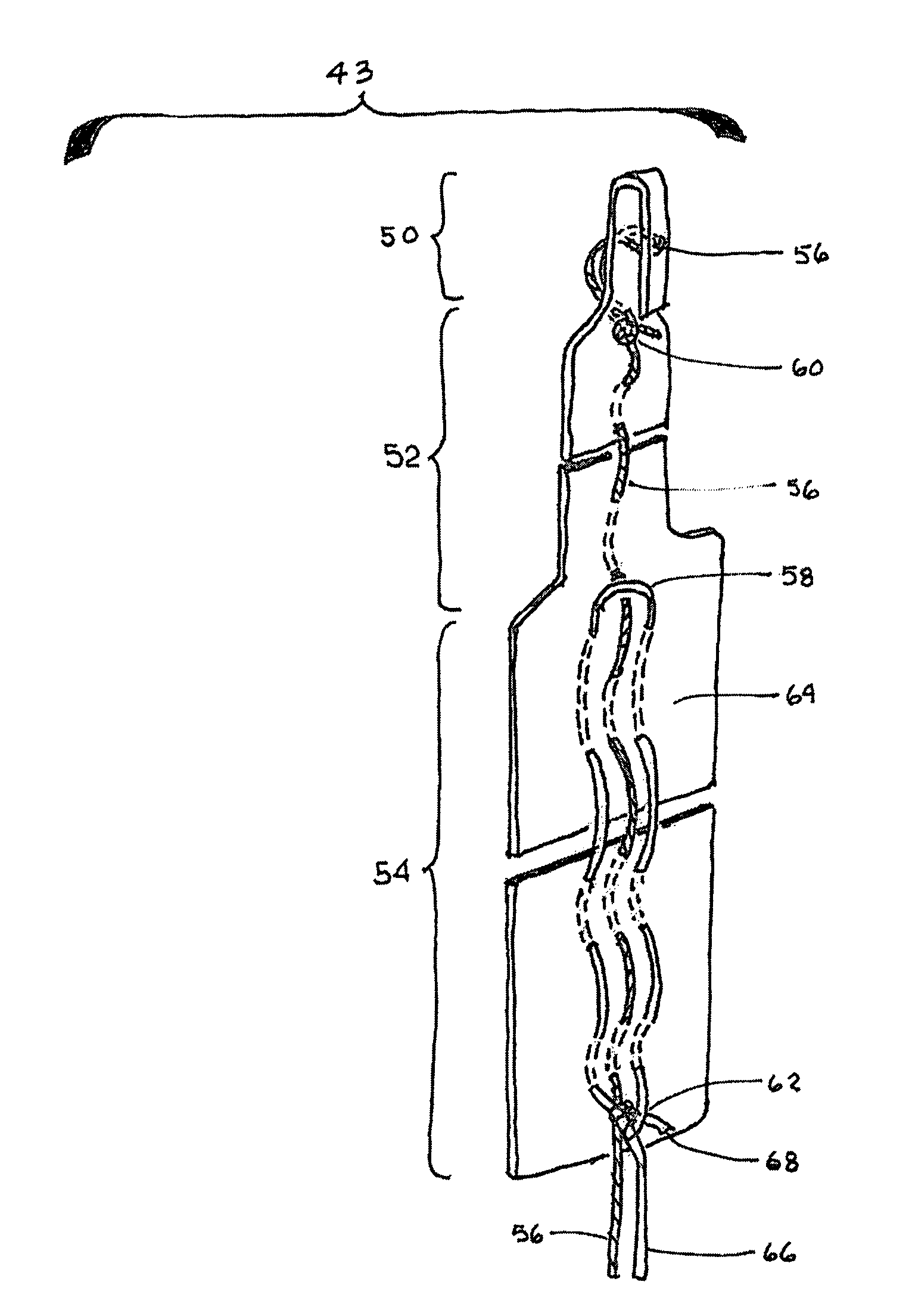
[0044]The closure device is made of a bunchable material that bunches within the tissue tract. The device is delivered in a delivery sheath through the introducer sheath through the tissue tract to a vessel having a puncture hole. The distal end of the device is seated against the vessel wall and material comprising the proximal section of the device is bunched within the tissue tract to provide an environment for blood coagulation, closure of the puncture hole and sealing the space within the tissue tract. The material of the device is a biocompatible material and can be partly or fully bioabsorbable or biodegradable.

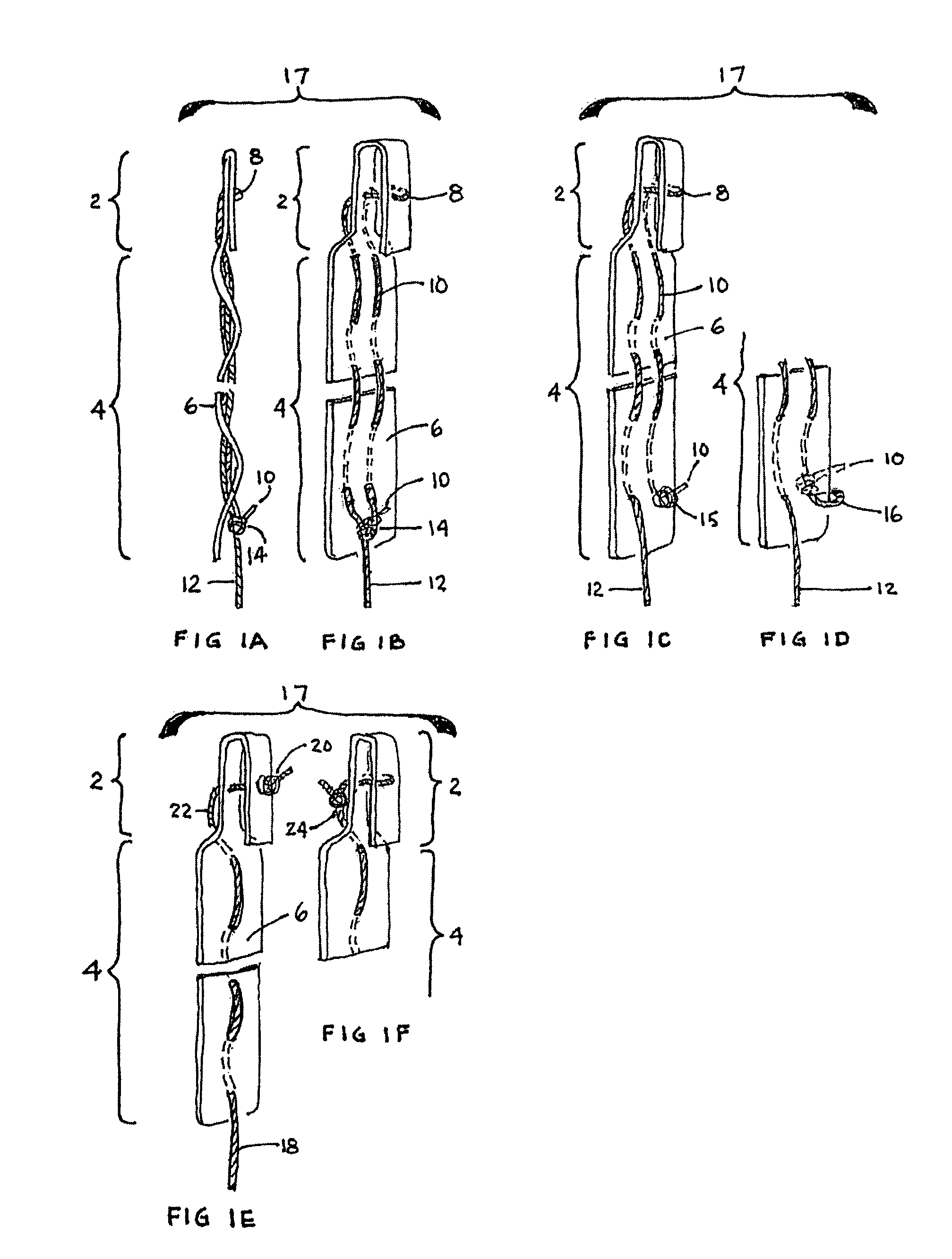
[0045]Turning now to the figures, FIG. 1A-1F depict the general embodiment of a device 17 having a distal section, a proximal section and a single tension member running through both the distal section and proximal sections and controlled by proximal ends that are proximal to the proximal section. That being said, FIG. 1A depicts a side view of an embodiment of device ...


PUM


Abstract

A closure device for closing a puncture wound has a distal section that can be placed against the interior wall of a vessel and a proximal section that bunches in the tissue tract to close the wound. One variation of the device provides for removing the distal section from the vessel so that it resides also in the tissue tract after the proximal section has been securely bunched and lodged within the tissue tract in order to provide unobstructed fluid flow in the vessel.

Description

FIELD OF THE INVENTION[0001]The invention is a closure device for closing a wound caused by a minimally invasive medical procedure that accesses the body through a vessel or cavity. The device and method of the invention provide for wound closure upon completion of such a minimally invasive procedure. The device is made of bunchable material that bunches in the tissue tract and provides a structural environment that stops bleeding and promotes healing of the tissue.BACKGROUND OF THE INVENTION[0002]Many vascular procedures can be accomplished by minimal invasion, typically by accessing the femoral artery or another major blood vessel, and through that vessel accessing the heart, brain, or other site that requires surgical attention. When the procedure is completed a hole remains in the accessed vessel that needs to be closed. The goal of repair of the puncture wound is to create hemostasis in the tissue tract, and to allow the puncture hole in the vascular lumen to seal, allowing blo...

Claims


Application Information

Patent Timeline
Patent Type & Authority Patents(United States)
IPC IPC(8): A61B17/08
CPCA61B17/0057A61B2017/00004A61B2017/00637A61B2017/2939A61B2017/00659A61B2017/0496A61B2017/00654
Inventor KEN, CHRISTOPHER G. M.
Owner KEN CHRISTOPHER G M
Why Eureka
Try Eureka