
Couplings for molten metal devices

a technology of molten metal and couplings, applied in the field of couplings, can solve the problems of longer component life, and achieve the effect of preventing any component damage and reducing wobbl

Inactive Publication Date: 2010-06-08
MOLTEN METAL EQUIP INNOVIATIONS LLC
View PDF353 Cites 68 Cited by
  • Summary
  • Abstract
  • Description
  • Claims
  • Application Information

AI Technical Summary

Benefits of technology

[0016]The present invention helps to alleviate the afore-mentioned problems by providing a coupling to maintain a rotor centered within the pumping chamber during operation of a molten metal pump, i.e., to help prevent nonconcentric movements that may cause the rotor to bump or rub or bump against the pump chamber or bearing surfaces. The rigid coupling of the present invention may include a counterweight to balance the coupling, and allows the rotor shaft and rotor to rotate with relatively little wobble.
[0017]Another aspect of the invention is a coupling for transferring gas into a shaft (preferably a rotor shaft) and a shaft configured to be used with the coupling. The coupling preferably includes a coupling member having a bore with an opening, the bore including an end proximal to the opening and an end distal to the opening. The distal end is preferably smooth and tapered with no threads. The coupling is preferably threaded at the proximal end, most preferably with coarse threads. The end of the shaft configured to be received in the bore has a mating smooth, tapered portion and mating coarse threads. When the end of the shaft is received in the bore, the tapered portion of the shaft is received in and aligns with the tapered, distal end of the bore, which assists in centering the shaft. Further, the mating of the smooth, tapered surfaces helps to prevent gas leaks thereby leading to longer component life.
[0018]The invention also relates to a motor-shaft-to-rotor-shaft coupling that does not include a physical connection between the rotor shaft and motor shaft. Therefore, in the event the rotor becomes jammed, the resulting torque overloads the coupling, and the drive from the motor and motor shaft are disconnected from the rotor shaft and rotor, thus helping to prevent any component damage.

Problems solved by technology

Further, the mating of the smooth, tapered surfaces helps to prevent gas leaks thereby leading to longer component life.

Method used


Image

  • Couplings for molten metal devices
  • Couplings for molten metal devices
  • Couplings for molten metal devices

Examples


Embodiment Construction

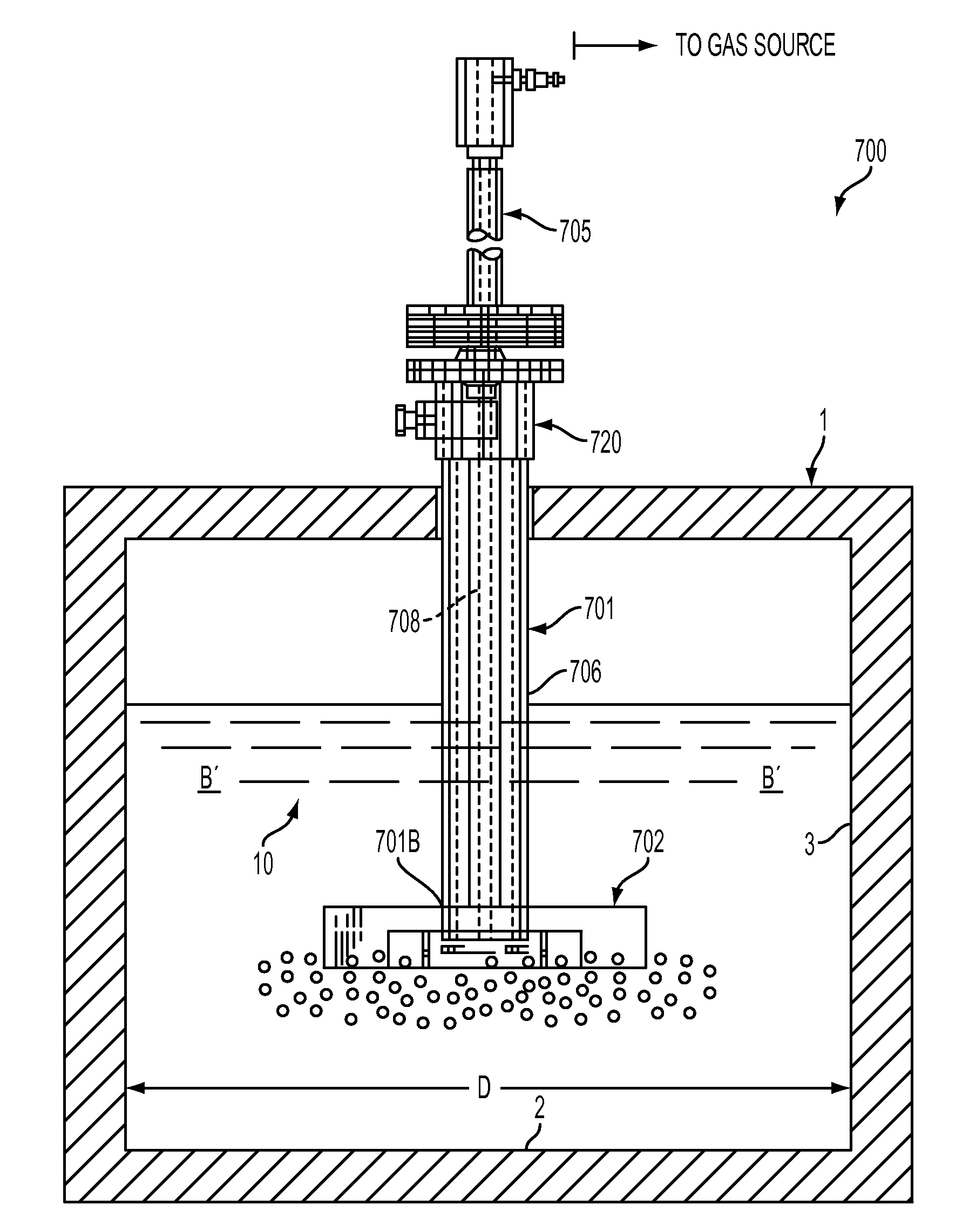
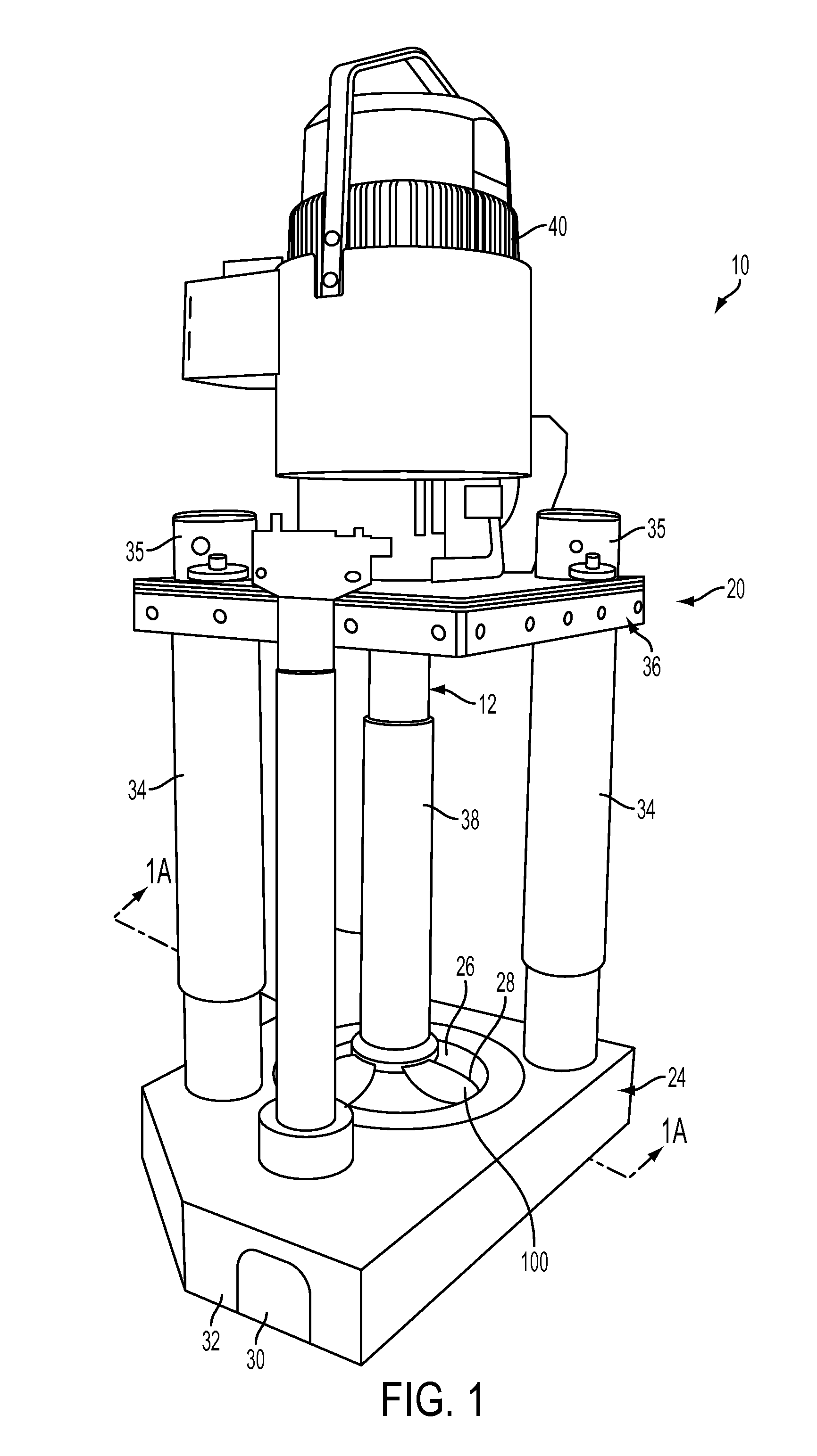
[0042]Referring now to the drawing where the purpose is to illustrate and describe different embodiments of the invention, and not to limit same, FIG. 1 shows a molten metal pump 10 in accordance with the present invention. System 10 includes a pump 20. For any device described herein, any of the components that contact the molten metal are preferably formed by a material that can withstand the molten metal environment. Preferred materials are oxidation-resistant graphite and ceramics, such as silicon carbide. Oxidation-resistant graphite is most preferred because of its relatively low cost and ease of manufacturing. Additionally, any of the components may be “protected components” as described in a co-pending U.S. Application entitled “Protective Coatings For Molten Metal Devices,” filed on Jul. 14, 2003, the inventor of which is Paul V. Cooper. The disclosure of this co-pending application is incorporated herein by reference.

[0043]Pump 20 is specifically designed for operation in ...


PUM


Abstract

Disclosed are couplings for use in devices positioned in a molten metal bath. One is a rigid coupling that may include a counterweight, the coupling to reduce nonconcentric movements during rotation of a shaft, particularly a rotor shaft. Another coupling uses magnetic force, rather than a direct physical connection, to form a driving connection between a drive shaft (such as a motor drive shaft) and a driven shaft (such as a rotor shaft). In the event the rotor is jammed, the increased torque creates an overload that disconnects the drive shaft from the driven shaft in order to help prevent damage to the rotor, driven shaft, drive shaft and other components. Also disclosed is a coupling to transfer gas into a shaft, the coupling having a non-threaded internal surface to help prevent gas leakage and thus assist in preventing any resulting damage to the coupling and shaft.

Description

CROSS REFERENCE TO RELATED APPLICATION[0001]This application claims the benefit of provisional application No. 60 / 395,471, entitled “Couplings and Protective Coatings for Molten Metal Devices,” filed on Jul. 12, 2002.FIELD OF THE INVENTION[0002]The invention relates to novel couplings that may be used in various devices, such as pumps, degassers and scrap melters used in molten metal baths. One aspect of the invention is a rigid coupling including a counterweight to generally maintain concentric rotation of the shaft. Another aspect of the invention is a rotor shaft to motor shaft coupling that decreases the possibility of breakage, maintenance and downtime in case the rotor is jammed. Another aspect is a shaft coupling for transferring gas that, among other things, decreases the possibility of gas leakage.BACKGROUND OF THE INVENTION[0003]As used herein, the term “molten metal” means any metal or combination of metals in liquid form, such as aluminum, copper, iron, zinc and alloys t...

Claims


Application Information

Patent Timeline
IPC IPC(8): F04B17/00F04D7/06F04D13/02F04D29/02
CPCF04D7/065F04D29/026F04D13/024F04D13/021F05D2300/171F05D2230/64
Inventor COOPER, PAUL V.
Owner MOLTEN METAL EQUIP INNOVIATIONS LLC
Features
  • Generate Ideas
  • Intellectual Property
  • Life Sciences
  • Materials
  • Tech Scout
  • Unparalleled Data Quality
  • Higher Quality Content
  • 60% Fewer Hallucinations
Learn More