Radiation imaging apparatus and radiation imaging system

a radiation imaging and apparatus technology, applied in the direction of optical radiation measurement, radiation controlled devices, instruments, etc., can solve the problems of difficult to irradiate a uniform light on the entire surface of the sensor unit, difficult to remove the effect, and non-uniform signal outpu

Active Publication Date: 2010-06-08
CANON KK
View PDF27 Cites 18 Cited by
  • Summary
  • Abstract
  • Description
  • Claims
  • Application Information

AI Technical Summary

Benefits of technology

[0009]As a typical method of correcting for such differences in the gains of each pixel, there is a gain correction. This gain correction is a technique in which a signal output derived by irradiating X-rays from an X-ray source no object is present, is stored in a memory (the signal output derived at this time is hereinafter referred to as a gain correction image), and based on this gain correction image, the signal output at the time of radiophotographing an object is corrected. Based on this gain correction image, the signal output (radiation image) at the time of radiographing the object is corrected by the method of division and the like, so that non-uniformity of the signal output generated by fluctuation of the gain for each pixel can be removed. Consequently, by dividing the signal output (radiation image) at the time of radiographing the object by the gain correction image, the fluctuation of the signal output can be corrected. That is, when gain correction is used, it is possible to remove the effect due to the non-uniformity of various parameters. In particular, the fact that the effect due to irradiation fluctuation of the X-ray source can be removed by the gain correction is the advantage of the digital X-ray imaging apparatus such as the FPD and the like as compared to the imaging apparatus using the film.
[0016]According to the present invention, gain correction can be performed based on the data (image signal) of the radiation image outputted from the sensor unit after the light not including image information is irradiated and the data of the gain correction image adaptable to each of the data of the radiation image outputted from the sensor unit without being irradiated with the light not including the image information. As a result, a gain correction image that can perform an appropriate gain correction according to the radiographing condition can be provided.

Problems solved by technology

That is, when gain correction is used, it is possible to remove the effect due to the non-uniformity of various parameters.
However, with the FPD disclosed in U.S. Pat. No. 5,905,772, when the light reset is performed, it is very difficult to irradiate a uniform light on the entire surface of the sensor unit.
Hence, in the signal output at the time of radiophotographing an object, a non-uniform signal output (apart from non-uniformities due to the presence of the object itself) may be generated.
Hence, the signal output at the time of radiographing an object has the possibility of being affected by this distribution as an artifact.
Hence, the signal output at the time of radiophotographing an object has the possibility of being affected by this.
Consequently, when the light reset is performed, even if gain correction is performed, there is the possibility that a sense of strangeness may be produced in the images.

Method used


Image

  • Radiation imaging apparatus and radiation imaging system
  • Radiation imaging apparatus and radiation imaging system
  • Radiation imaging apparatus and radiation imaging system

Examples


first embodiment

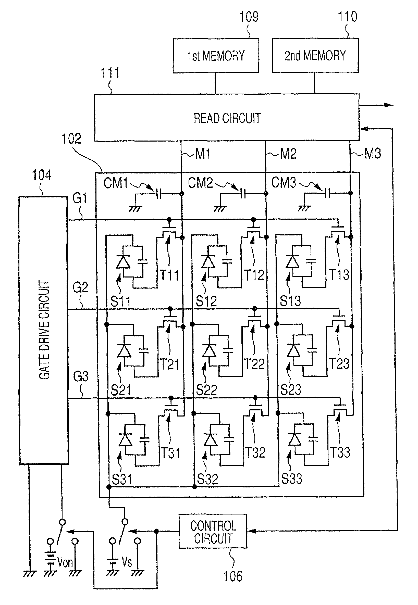
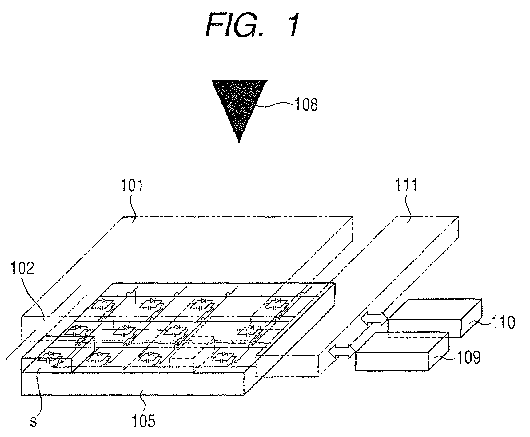
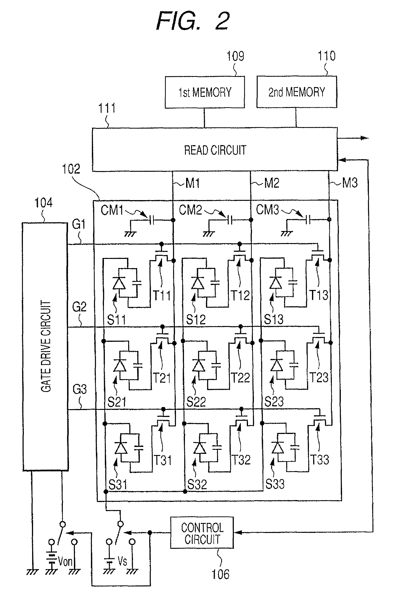
[0027]Hereinafter, with reference to the drawings, a first embodiment of the present invention will be described. FIG. 1 is a view showing one example of the configuration of a radiation imaging apparatus of the present embodiment. Incidentally, in the present embodiment, description will be made with reference to the case where the radiation imaging apparatus is an FPD.

[0028]In FIG. 1, the FPD has a phosphor 101 that converts X-rays, which are one example of a type of radiation, into light. This phosphor 101 has any one of, for example, Cd2O3, Cd2O2S, and CsI as a main ingredient.

[0029]Further, the FPD has a sensor unit sensor unit 102 configured such that a plurality of photoelectric conversion elements S11 to S33 for converting light into an electrical signal are disposed in a matrix pattern on an insulating substrate having a light transmission property. Incidentally, in FIG. 2, the number of photoelectric conversion elements S provided in the sensor unit 102 is nine. However, i...


PUM


Abstract

The invention intends to be able to perform a gain correction fully adequately. Hence, at the time of radiographing an object, a gain correction of the object image is performed based on a gain correction image (XRc1) derived by performing a light reset. On the other hand, at the time of radiographing an object, when a light reset is not performed, a gain correction of the object image is performed based on a gain correction image (XRc2) derived without performing the light reset.

Description

BACKGROUND OF THE INVENTION[0001]1. Field of the Invention[0002]The present invention relates to a radiation imaging apparatus, a radiation imaging system, and a correction method of an image, and in particular, it is suitable for use to correct the data of an image.[0003]2. Description of the Related Art[0004]In recent years, demand for digitalization of X-ray images radiographed in hospitals has been on the increase. Hence, in place of the X-ray imaging apparatus that performs radiographing based on a film, a flat digital X-ray imaging apparatus (flat panel detector: hereinafter referred to as FPD) has began to be used. The FPD is an apparatus that converts radiation into an electrical signal based on a plurality of radiation detecting elements disposed in a two-dimensional array pattern. The radiation detecting element mainly uses a non-monocrystalline semiconductor such as amorphous silicon (hereunder referred to as a-Si) capable of being formed into a large area detector. Such ...

Claims


Application Information

Patent Timeline
Patent Type & Authority Patents(United States)
IPC IPC(8): G01T1/24
CPCH04N5/32H04N5/357H04N5/378H04N5/361H04N5/365H04N5/374H04N25/67H04N25/60H04N25/63H04N25/76H04N25/75
Inventor YOKOYAMA, KEIGOENDO, TADAOKAMESHIMA, TOSHIOYAGI, TOMOYUKITAKENAKA, KATSURO
Owner CANON KK
Why Eureka
Try Eureka