

Radio resource management method, management apparatus employing the same, base station, and terminal
- Summary
- Abstract
- Description
- Claims
- Application Information
AI Technical Summary
Benefits of technology
Problems solved by technology
Method used
Image

Examples
first embodiment
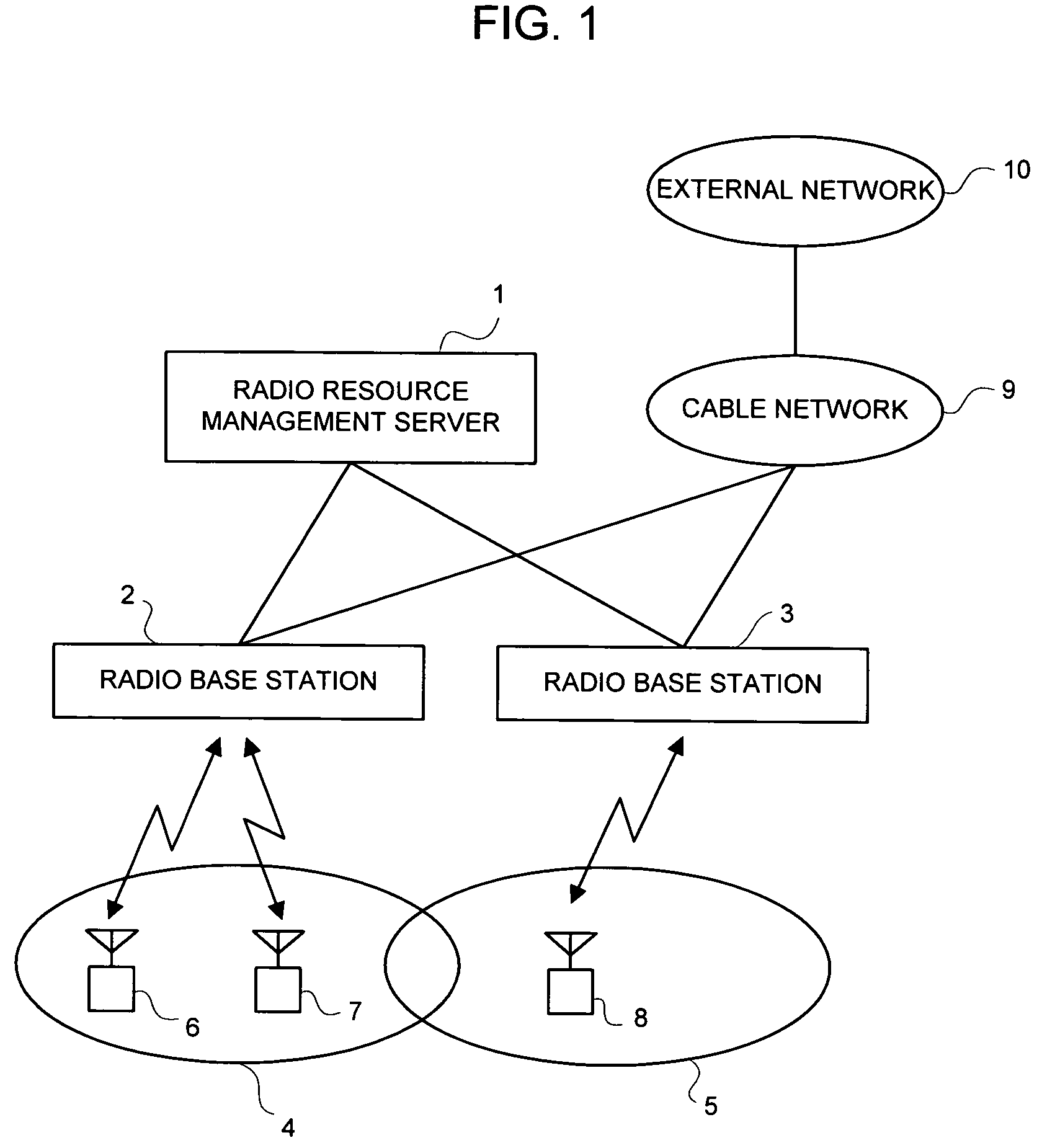
[0059]Embodiments of the present invention will be explained below in detail by referring to the attached drawings. FIG. 1 is a schematic diagram illustrating the outline of a system to which the present invention is applied. A radio resource management server 1 manages radio resources in the radio communication system. The radio resource management server 1 includes as followers radio base stations 2 and 3, which include service areas 4 and 5, respectively. For example, as shown in FIG. 1, the service area 4 includes radio terminals 6 and 7 while the service area 5 includes a radio terminal 8. The radio base stations 2 and 3 are connected to an external network 10 via a cable network 9.
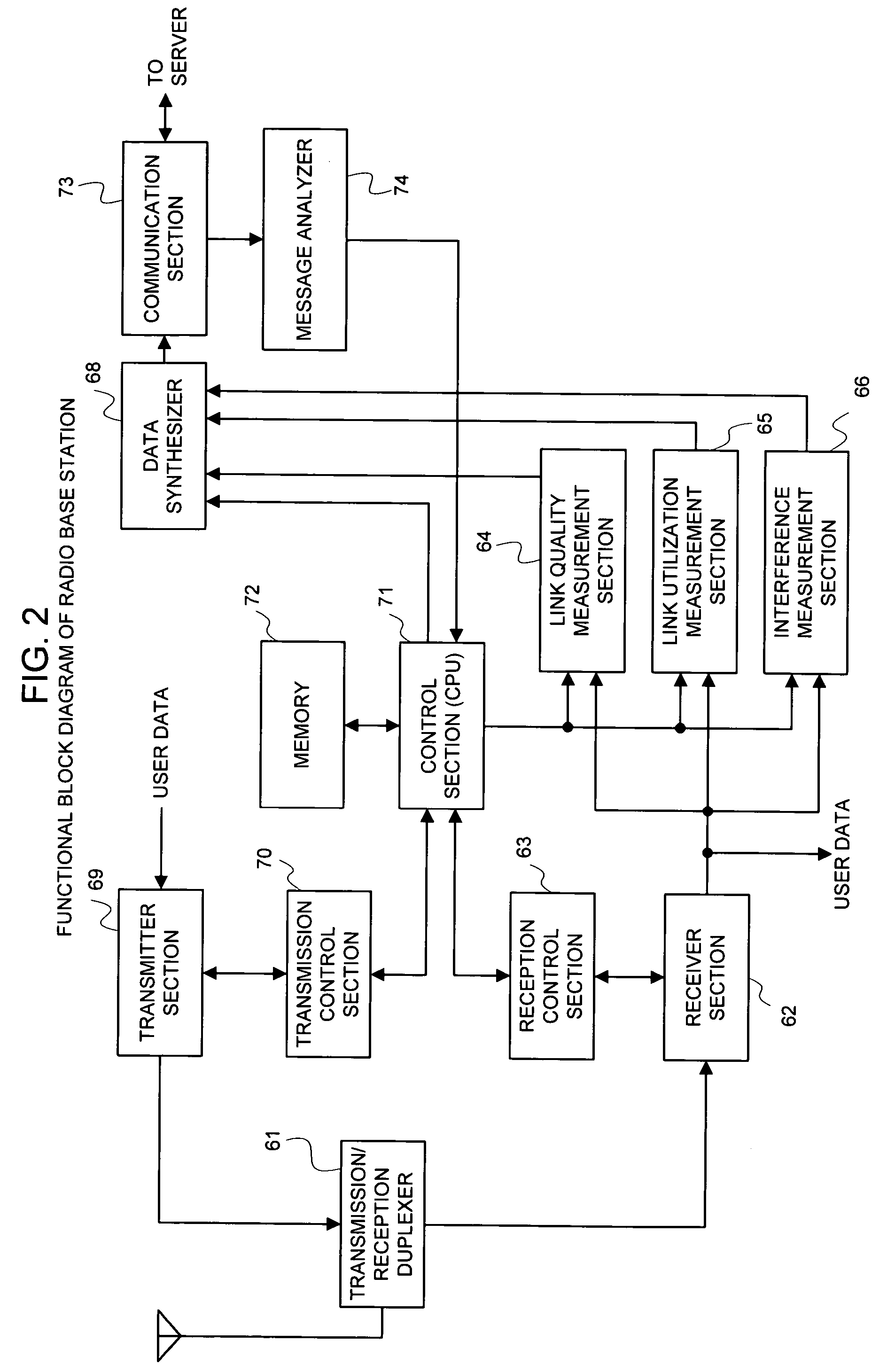
[0060]FIG. 2 is a schematic block diagram illustrating the function of a radio base station. A transmitter section 69 performs a transmission process of downstream user data (or packet data) and transmits the processed data to a radio terminal via a transmission / reception duplexer 61 and an antenna. ...
second embodiment
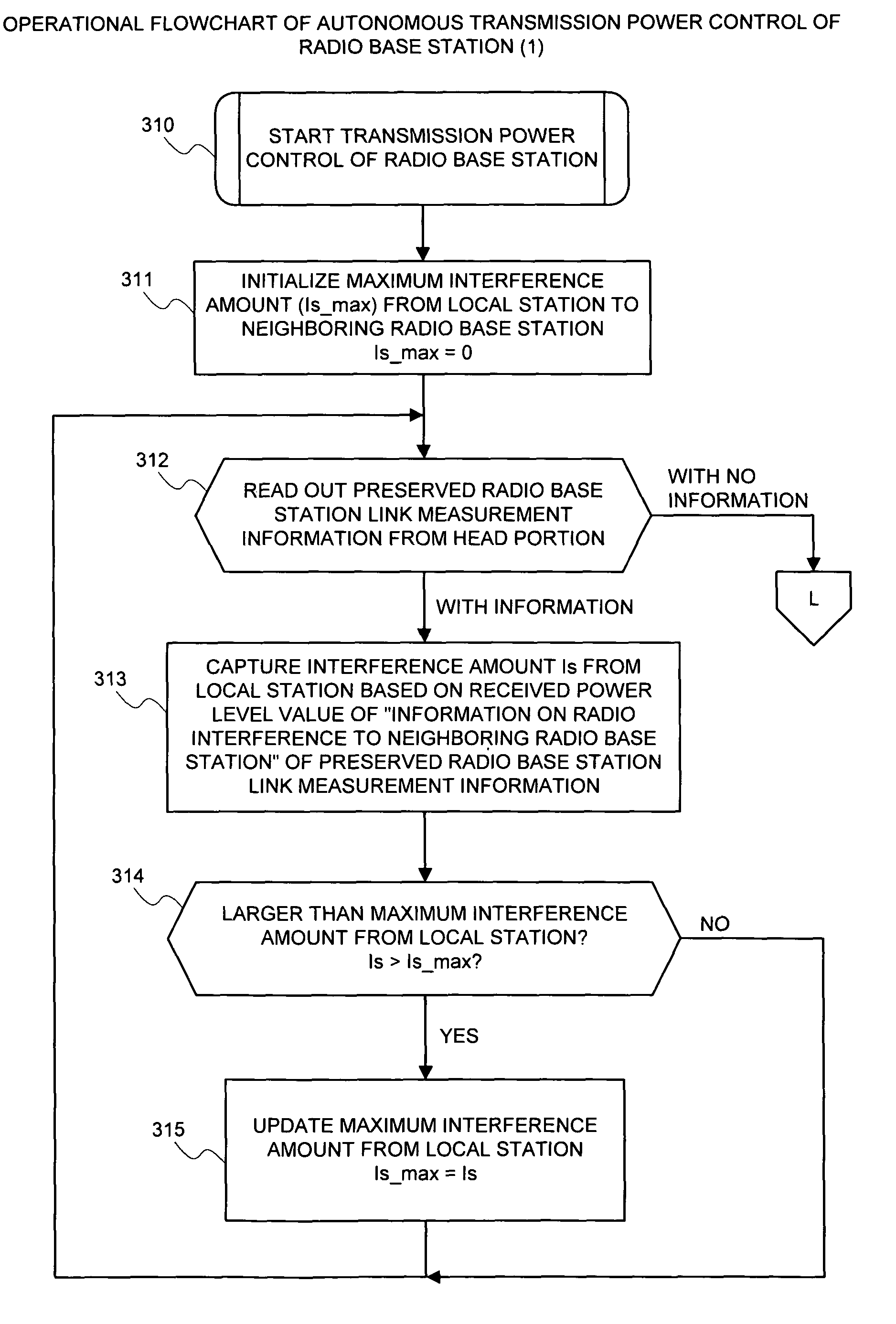
[0080]Each of FIGS. 11 and 12 is an operational flowchart for the second embodiment according to the present invention. It is now assumed that respective radio base stations communicate (or broadcast) the radio link measurement information shown in FIG. 4 mutually to other neighboring radio base stations and save radio link measurement information notified from other station. First, the maximum interference amount Is_max from the local station to a neighboring radio base station is initialized to “0” (step 311). Then, the radio base station link measurement information saved is read out (step 312). Thus, the interference amount is from the local station is captured based on the received power level value in “information on a radio interference with a neighboring radio base station” (step 313).
[0081]It is decided whether or not the interference amount from the local station is at maximum. Decision is made by comparing the interference amount Is from the local station with the maximum...
third embodiment
[0086]FIG. 14 is a flowchart showing the operation of a radio terminal according to the present invention. A radio terminal initializes after booting, sets a frequency channel or a transmission power, and links to a neighboring radio base station. Then, the radio terminal obtains information such as the address thereof or the address of the radio resource management server and then performs various configurations (step 421). Next, the radio terminal activates the timer T2 (step 422) and then becomes an event waiting state (step 423). The value of the timer T2 determines the interval at which the radio terminal notifies the radio resource management server of the radio link measured result.
[0087]Every time the timer T2 reaches a timeout, the radio terminal captures the radio link quality information to a radio base station during communication (step 424), the radio link utilization information to a radio base station during communication (step 425), and the link quality information (...
PUM
 Abstract
Description
Claims
Application Information