Crawl space encapsulation system

a space encapsulation and claw technology, applied in the field of claw space encapsulation system, can solve the problems of destroying the materials used in the foundation building, unhealthy for the home occupant, and the inability to attach the vapor barrier material directly to the sill plate,

Inactive Publication Date: 2010-06-15
SHIPSTON LORRI B +1
View PDF18 Cites 29 Cited by
  • Summary
  • Abstract
  • Description
  • Claims
  • Application Information

AI Technical Summary

Benefits of technology

[0014]By combining a vapor barrier with foam insulation into a single product, the need for additional rigid foam board on the walls or for dr

Problems solved by technology

Rain and snow permeate the soil, so moisture easily develops in the space between the ground and the flooring which is destructive to the materials used in building the foundation and unhealthy for the home occupant.
Heating and cooling costs can be significantly higher for homes that have a crawl space vented by either a passive or a mechanical air flow system.
Howeve

Method used


Image

  • Crawl space encapsulation system
  • Crawl space encapsulation system
  • Crawl space encapsulation system

Examples


Embodiment Construction

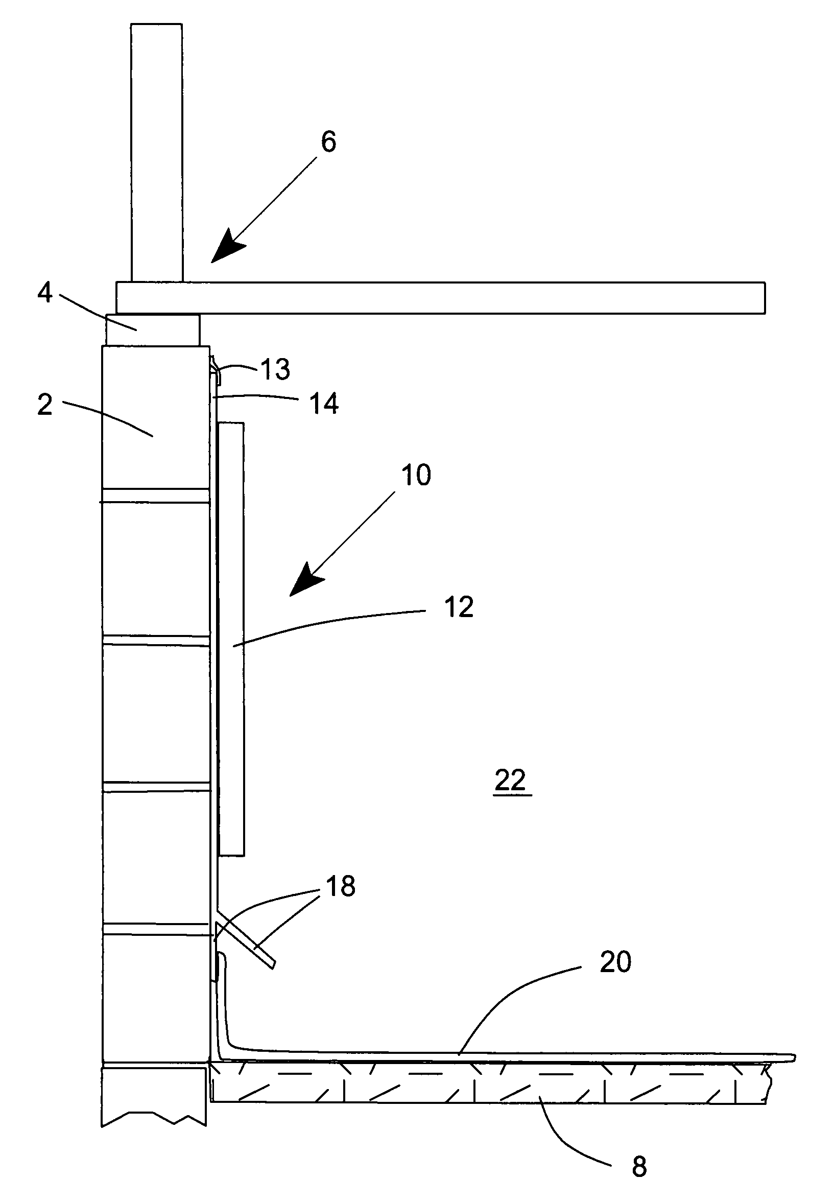
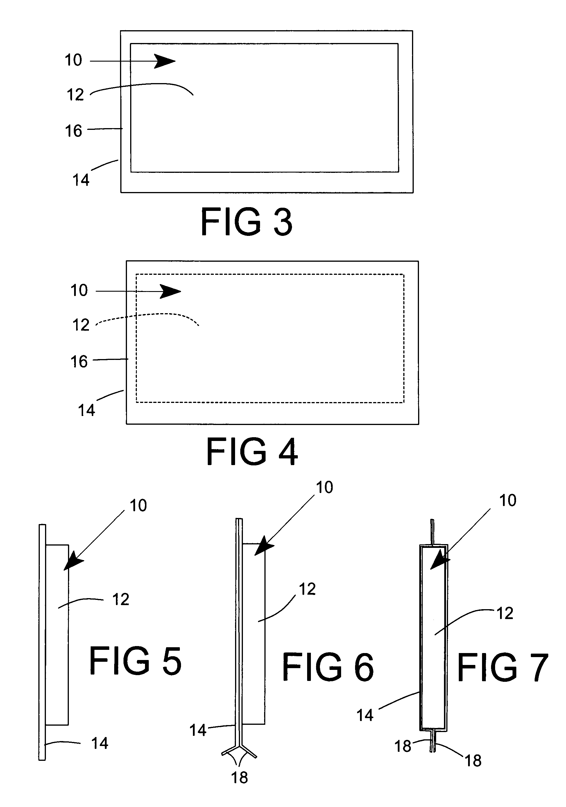
[0038]Several versions of a laminated vapor barrier 10 are depicted in FIGS. 1-8 and 11-19. These laminated insulated vapor barriers 10 include both an insulating foam member 12 and at least one liner layer 14. Since the thickness of the liners 14 is less than the thickness of the foam members 12, the drawings are not necessarily to scale, because the liners 14, and their features could not otherwise be clearly represented.

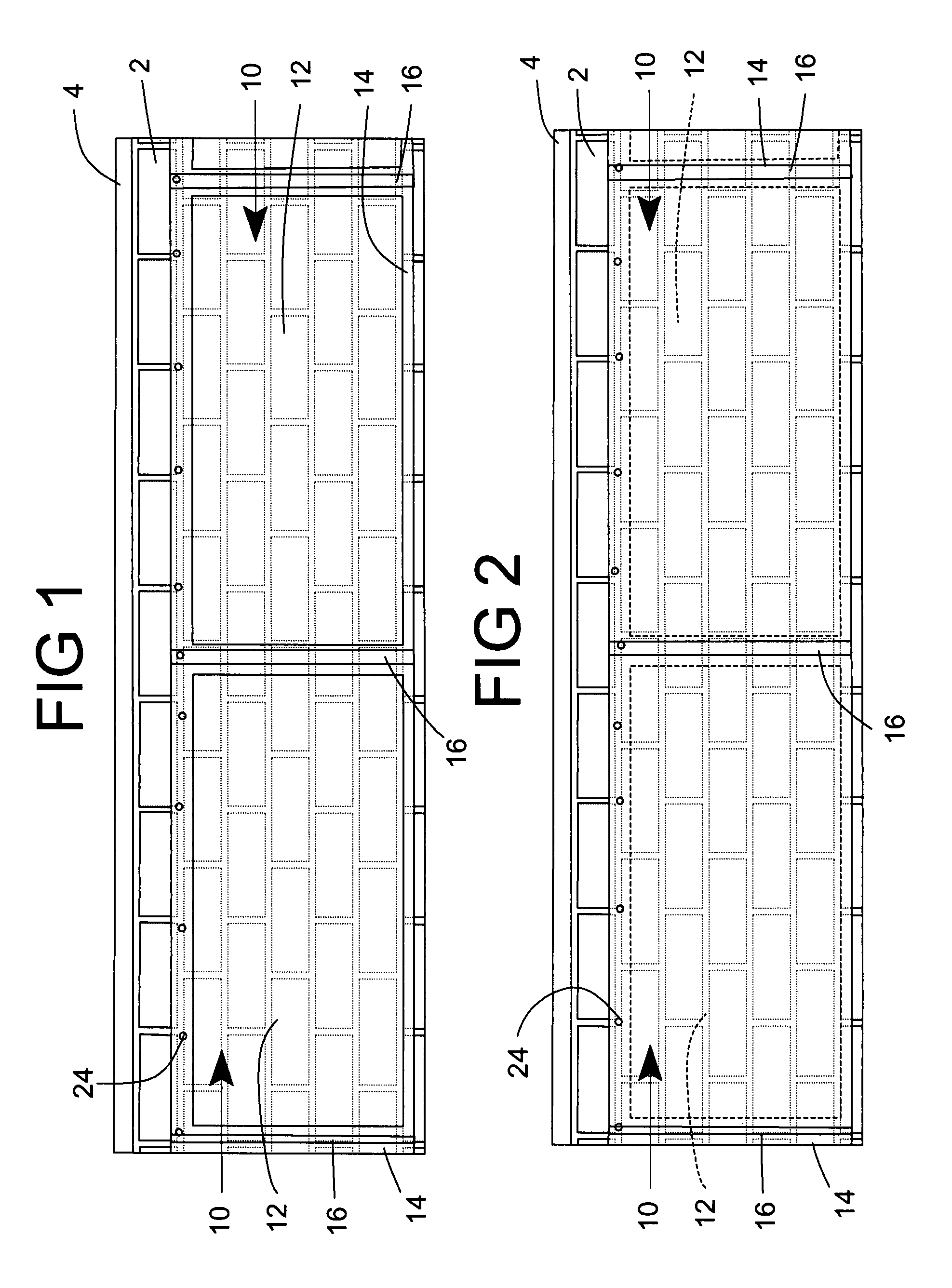
[0039]FIGS. 1 and 2 show two versions of an insulating vapor barrier 10 according to this invention, in which the insulating vapor barrier is mounted on a block wall 2 below the sill plate 4 in a crawl space. FIGS. 3 and 4 show individual insulating vapor barrier panels 10 that correspond respectively to FIGS. 1 and 2. FIG. 1 shown a version in which the insulating vapor barrier 10 includes an insulating foam member 12 laminated to a liner 14, which is positioned between the block wall 2 and the insulating foam member 12. The liner 14 comprises a sheet layer that ...


PUM

PropertyMeasurementUnit
Thicknessaaaaaaaaaa
Thicknessaaaaaaaaaa
Thicknessaaaaaaaaaa

Abstract

A system for forming an insulating vapor barrier in a building is especially suited for forming an insulating vapor barrier in a crawl space beneath a building. The system includes a series of separate vapor barrier panels that can be attached around a wall. A ground level vapor barrier can be sealed to the insulating vapor barrier panels, which can be sealed to each other and along a top edge to the wall. The individual vapor barrier panels include an insulating foam member with a vapor resistant liner laminated thereto and extending beyond the edges of the insulating foam member to provide space for securing and sealing multiple vapor barrier panels to form a continuous insulating vapor barrier. Mechanical or hook and loop fasteners can be provided to secure the top edges of the vapor barrier liners to the wall and bottom edges to a ground liner.

Description

CROSS REFERENCE TO PRIOR CO-PENDING APPLICATIONS[0001]This application claims the benefit of prior filed, U.S. Provisional Patent Application Ser. No. 60 / 773,617 filed Feb. 16, 2006.FIELD OF THE INVENTION[0002]The present invention relates to a system used to encapsulate a crawl space, a plastic laminate using both a film and a polyolefin foam or a film and an expandable polystyrene foam. The encapsulating system enhances clean airflow, significantly reduces mold spore production, prevents pest migration, and prevents certain moisture damage from attacking the foundational carpentry of a residential structureBACKGROUND OF THE INVENTION[0003]Homes are often built with crawl spaces underneath substantially all or a significant portion of the structure. The crawl space is typically left in a natural state with open soil left in the condition that existed prior to and after the building was completed. The foundation of a home is usually concrete and cinder blocks that support lumber flo...

Claims


Application Information

Patent Timeline
IPC IPC(8): E04B1/62B32B27/00E02D19/00
CPCB32B5/18B32B27/30E04B1/70E04B1/0007B32B27/32
Inventor SHIPSTON, LORRI B.PAVLANSKY, MARK
Owner SHIPSTON LORRI B
Why Eureka
Try Eureka