
Pulsed detonation engines manufactured from materials having low thermal stability

a technology of thermal stability and pulsating detonation engine, which is applied in the direction of marine propulsion, vessel construction, aircraft navigation control, etc., can solve the problems of high cost of thermal stability materials, increase in engine response time, and increase in the minimum thrust pulse duration and engine response time. , to achieve the effect of low thermal stability and easy motion correction

Active Publication Date: 2010-06-15
LEIDOS +1
View PDF4 Cites 25 Cited by
  • Summary
  • Abstract
  • Description
  • Claims
  • Application Information

AI Technical Summary

Benefits of technology

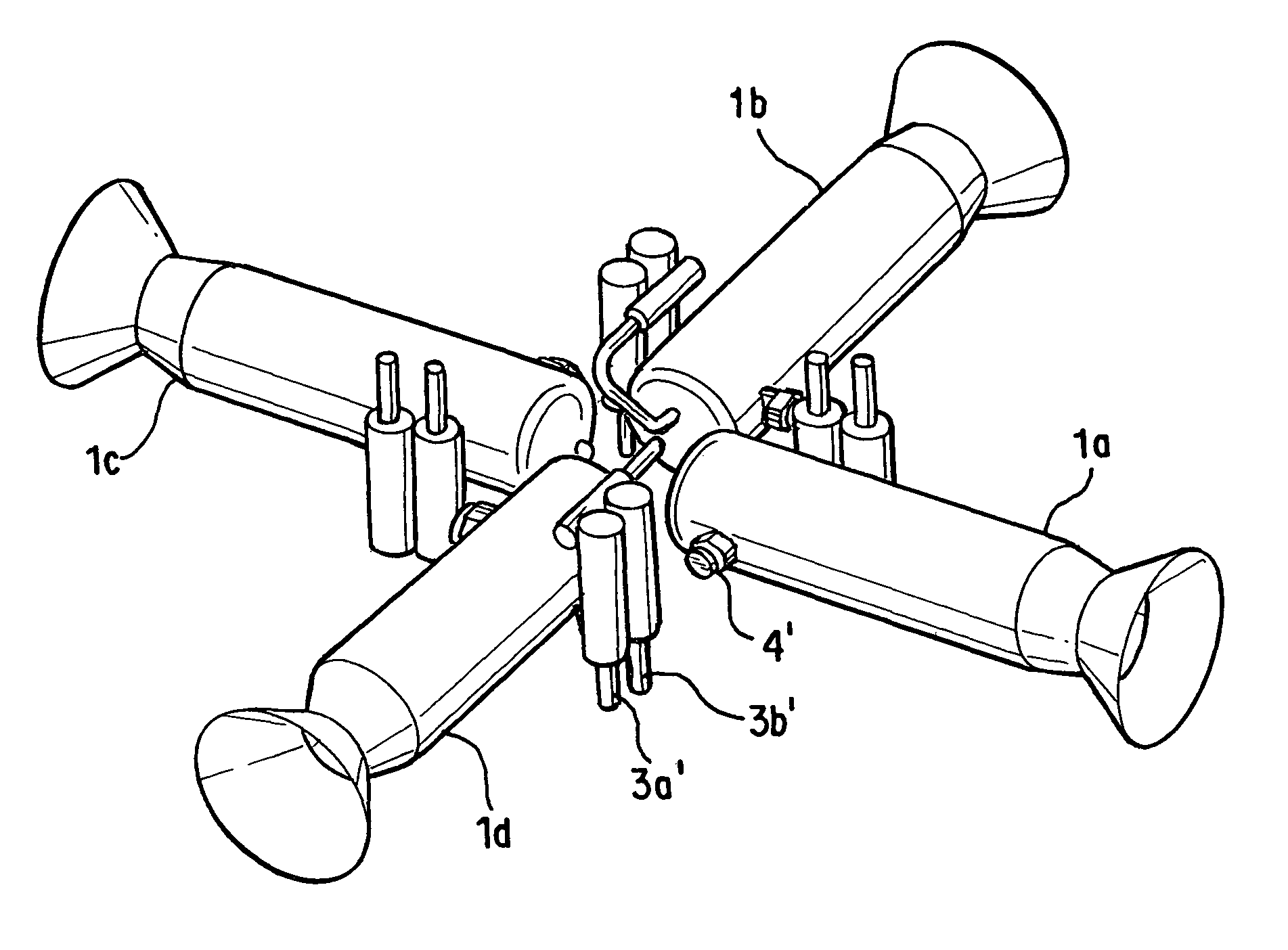
The present invention relates to a pulsed detonation engine (PDE) that can be made from low thermal stability materials, such as plastics and composites, without causing dimensional failure. The PDE is particularly useful in applications such as reaction control systems (RCS) thrusters for orbital correction and control, and missiles trajectory correction and motion control. The method involves actuating the PDE for a single thrust impulse or a sequence of impulses for time intervals that do not allow the engine components to reach a temperature that would result in dimensional failure. The thrust generated during the interval is useful for such applications as orbital control. The PDE can be assembled into RCS that facilitate motion correction in a number of directions, where two or more of the PDEs can be actuated simultaneously or alternatively.

Problems solved by technology

Such highly thermally stable materials are expensive, leading to high costs for the rocket systems.
In addition, the need to raise the temperature in the combustion chamber before engine operation leads to an increase in minimum thrust pulse duration and engine response time.
Together these factors negatively affect the controlling capability of the engine, which is especially important in such applications as reaction control systems (RCS) or auxiliary rocket propulsion systems.
Such maximum temperatures exceed the thermal stability limits for most plastics, light metals, fiber-reinforced composites, and other lightweight materials, rendering these materials unsuitable for use in conventional PDEs.

Method used


Image

  • Pulsed detonation engines manufactured from materials having low thermal stability
  • Pulsed detonation engines manufactured from materials having low thermal stability
  • Pulsed detonation engines manufactured from materials having low thermal stability

Examples


Embodiment Construction

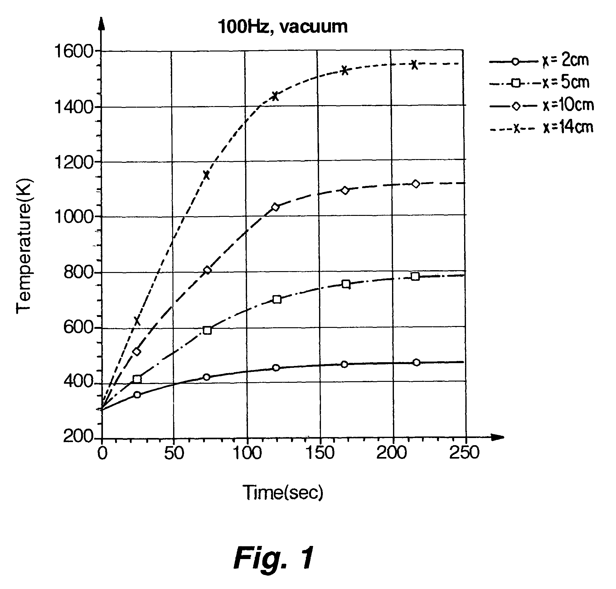
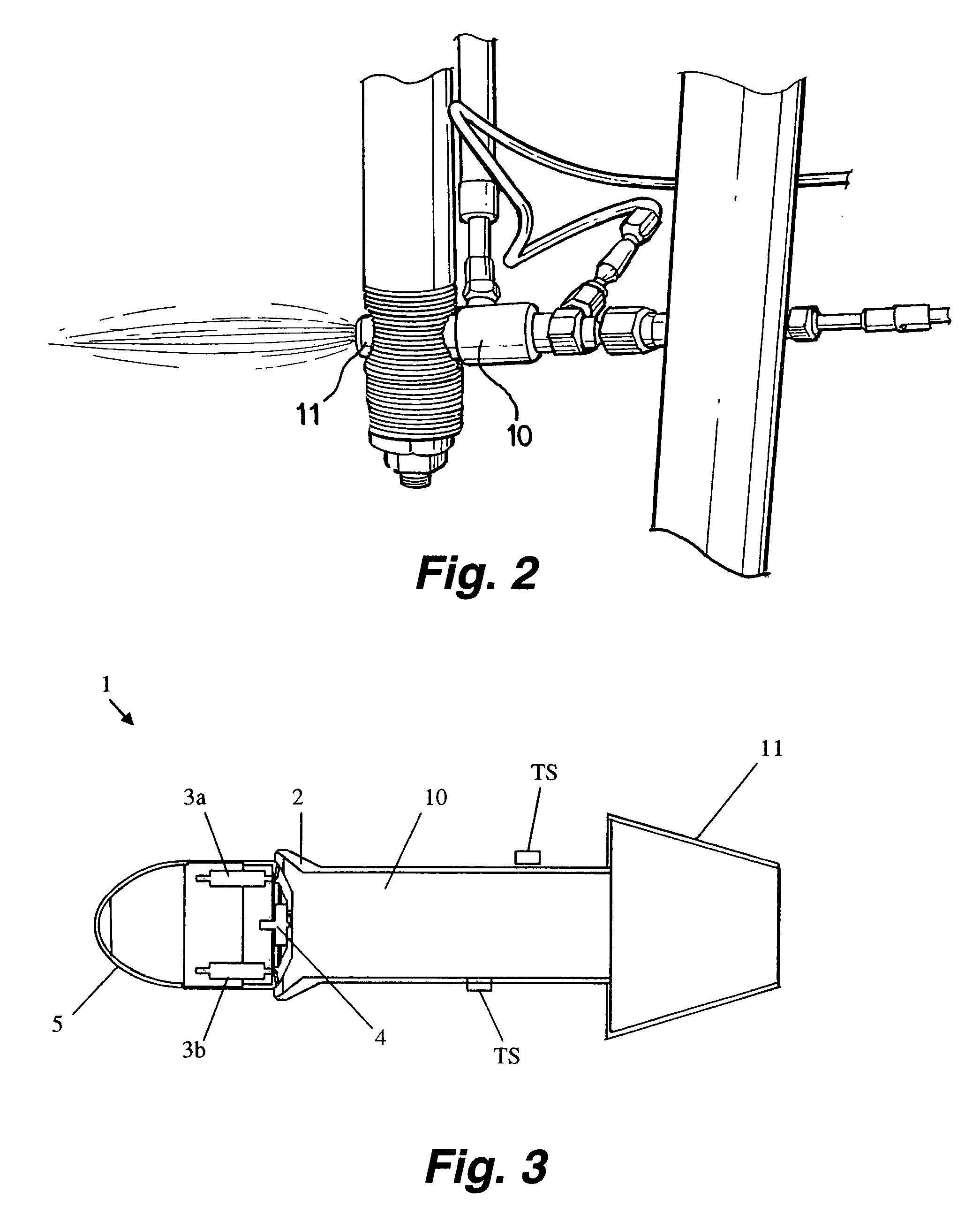
[0015]The pulsed detonation engine (PDE) of the present invention operates by intermittent injection and detonation, thereby producing thrust without requiring that the engine volume be pre-heated prior to operation, as is required for operation of conventional rocket engines. The intermittent injection of the relatively low-temperature reactants cools the engine volume between detonations, leading to only a gradual temperature rise during engine operation. Because only short intervals of operation are needed for many applications, such as the use of reaction control system (RCS) engines for orbit control, the detonation chamber wall does not reach temperatures that lead to dimensional failure of the materials having low thermal stability.

[0016]Materials described herein as having “low thermal stability” refer to materials exhibiting good dimensional stability at low-to-moderate temperatures, but which exhibit melting, softening, decomposition, or other loss of dimensional stability...


PUM


Abstract

Pulsed detonation engines (PDEs), or various components thereof, such as the detonation chamber and / or nozzle, can be economically constructed from materials having low thermal stability, such as plastics, composites, and light metals. During operation, the intermittent injection and detonation of reactants produces a motive force (e.g., thrust) over relatively short intervals useful in orbit control and the like. The relatively short intervals of operation prevent temperatures of the PDE components from reaching temperatures that would result in their dimensional failure.

Description

STATEMENT OF FEDERALLY SPONSORED RESEARCH[0001]This invention was made pursuant to U.S. Army Missile Defense Command and Enigmatics Inc. contract number DASG 60-99-C-0045, and the U.S. Government therefore may have certain rights in the invention.FIELD OF THE INVENTION[0002]The present invention is directed to pulsed detonation engines, and more particularly to pulsed detonation engines having components manufactured from plastics and / or other materials having low thermal stability.DESCRIPTION OF RELATED ART[0003]In conventional rocket engines, reactive materials are injected into a combustion chamber in which the materials react at high pressure and high temperature in a continuous flow process. After reaction in the combustion chamber, the reaction products expand through a converging / diverging nozzle, reaching high velocities thereby generating thrust. In general, the efficiency of the conventional rocket engine is a function of the temperature in the combustion chamber. Because ...

Claims


Application Information

Patent Timeline
Patent Type & Authority Patents(United States)
IPC IPC(8): F02K5/02
CPCB64G1/40F02K9/68F02K9/60Y10S60/909
Inventor EIDELMAN, SHMUELLIANOS, DIMITRIOS
Owner LEIDOS
Learn More