Latch for suppressor

a technology for latching suppressors and sound suppressors, which is applied in the direction of muzzle attachment, weapon components, weapons, etc., can solve the problems of excessive steps or movements to attach/detach, poor support and insufficient bearing surfaces of the mount, etc., to enhance the sound reduction potential of the suppressor, tighten the baffle, and limit the amount of rotational movement of the suppressor

Inactive Publication Date: 2010-06-15
WILSONS GUN SHOP
View PDF13 Cites 28 Cited by
  • Summary
  • Abstract
  • Description
  • Claims
  • Application Information

AI Technical Summary

Benefits of technology

[0021]A third unique improvement is the ability to compensate for the tolerances of the standard flash hider used on the M4 Series Carbine, the M16 Series Rifle and their commercial equivalent firearms. This ensures that a tighter bore through the baffles within the suppressor is possible, thereby enhancing the sound reduction potential of the suppressor. This is achieved through the use of a simple compression spring that acts upon the flash hider in relation to the bore of the suppressor mount. As the primary latch plate is pressed down into the two grooves in the flash hider, a spring is compressed on the inside of the primary latch thus biasing the bore of the mount in the suppressor against the outside diameter of the flash hider. This means that any diametrical clearance between the flash hider and the bore of the suppressor is taken up by the spring, resulting in the minimization of the angular deviation between the center line of the flash hider and the center line of the bore through the suppressor.
[0022]A fourth unique improvement is that the suppressor is rotationally indexed to the flash hider when attached, thus limiting the amount of rotational movement of the suppressor. The vertical primary latch has a protruding surface on one side that interfaces with one of the wrench flats that are machined into the standard flash hider for the M4 Series Carbine, the M16 Series Rifle and their commercial equivalents. These wrench flats are used to tighten the flash hider onto the rifle and when the flash hider is attached correctly to the rifle, these wrench flats are oriented in a position that is vertical to the axis of the bore of the rifle. When the vertical primary latch plate is pushed down to its fully down position, the protruding surface abuts one of the wrench flats and thus rotationally indexes the suppressor to the flash hider.
[0023]A fifth unique improvement is that the primary latch plate is supported well enough in its fully unlocked position such that it cannot move far enough off of the axis of the track for the latch plate within the suppressor for the primary latch plate to wedge in place, inhibiting its downward movement. The primary latch plate was designed such that the straight portion of the legs extend below the centerline of the suppressor and necessary clearance was provided in the recess machined into the suppressor for accommodate those longer legs. As a result the primary latch plate is much better constrained within the track when in its fully unlocked position.

Problems solved by technology

However, they all have problems including the length of time it takes to attach / detach the suppressor from the flash hider, excessive steps or movements to attach / detach the suppressor, poor support and insufficient bearing surfaces of the mount interface to the flash hider, inability to remove when the suppressor is hot, and excessive thermal transfer to the latch from the mount and the suppressor body.
The main problem with this system is that the collet fingers are basically a form of flat spring and because they surround and are in direct contact with the flash hider, there is considerable transfer of heat to the collet fingers.
During prolonged weapon firing the temperature of the collet fingers reaches a point, which is dictated by their heat treatment and metallurgical properties, where the spring characteristics of the collet fingers will become reduced resulting in failure of the fingers to retract out of the flash hider and thus locking the suppressor to the firearm.
The main problem with the Vaden approach is the inability to activate the lock when the suppressor is hot without the use of special tools or heat resistant materials to protect the operator's hands.
Additionally Vaden utilizes a long thread engagement on the rotating collars so it takes considerable motion and time to lock / unlock the system.
While this mount is secure, the three main problems are the excessive time to attach / detach, the inability to remove a hot suppressor without tools or thermal protection for the operator and the collar being a separate part which is therefore prone to loss.
The problem with this mounting system is that the steps to mount and dismount the suppressor are numerous.
By cutting the track lower into the suppressor and making the latch plate longer, the current design can no longer deflect far enough off axis to its vertical track to bind and thus inhibit its downward travel as locking occurs.

Method used


Image

  • Latch for suppressor
  • Latch for suppressor
  • Latch for suppressor

Examples


Embodiment Construction

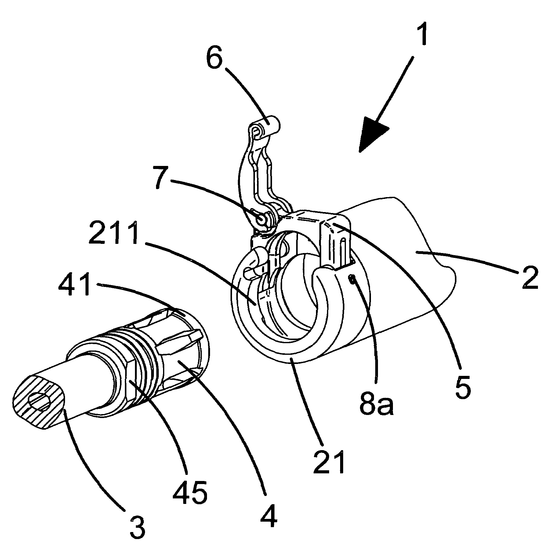
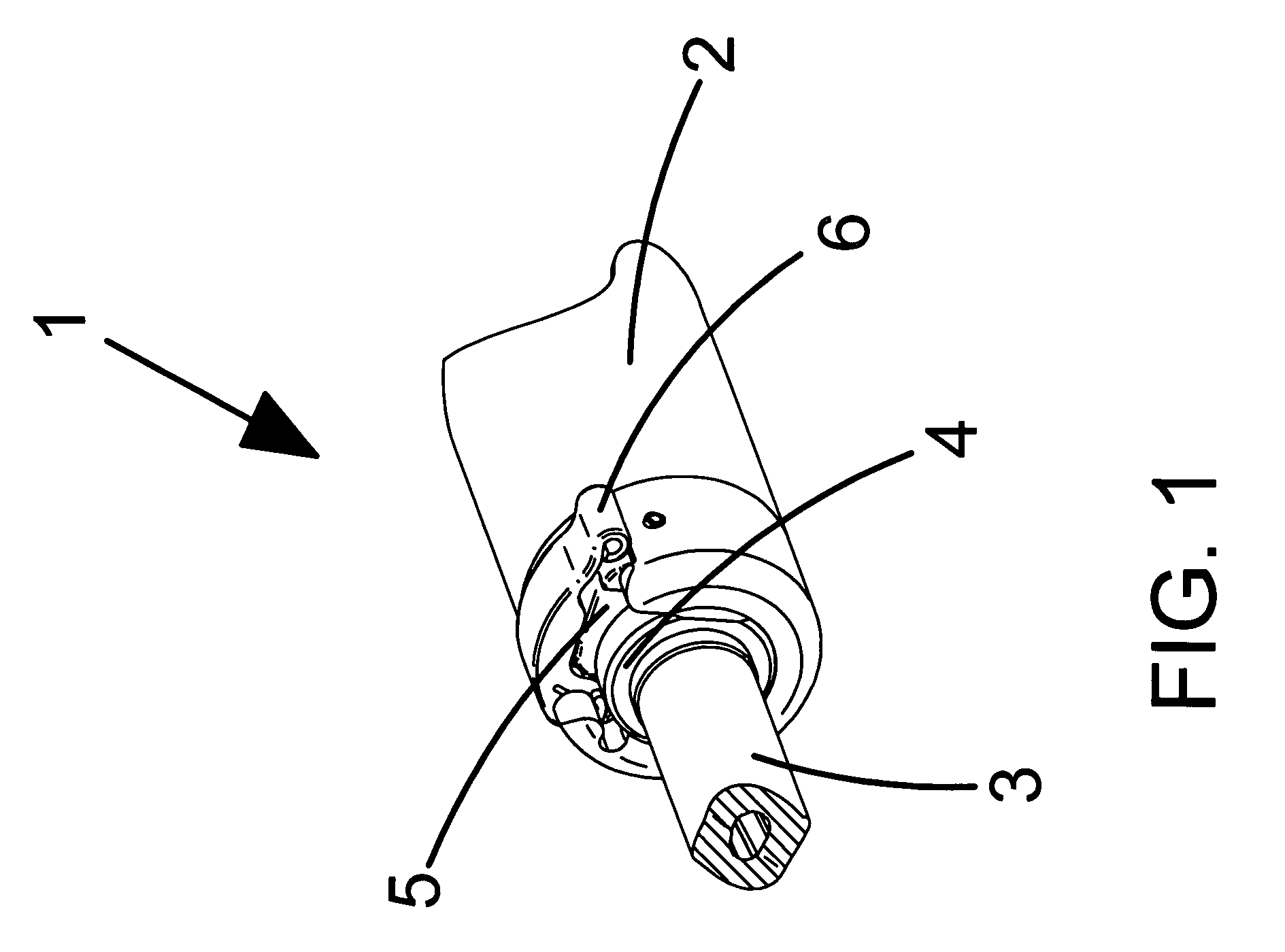
[0032]Referring in detail to FIG. 1 of the drawings, suppressor latch assembly 1 is shown in the fully latched condition. Suppressor body assembly 2 surrounds flash hider 4 which is attached to firearm barrel 3. Primary latch plate 5 is in the fully latched position as is secondary latch 6. In this position flash hider 4 is restrained from withdrawing from suppressor body assembly 2 by primary latch plate 5.

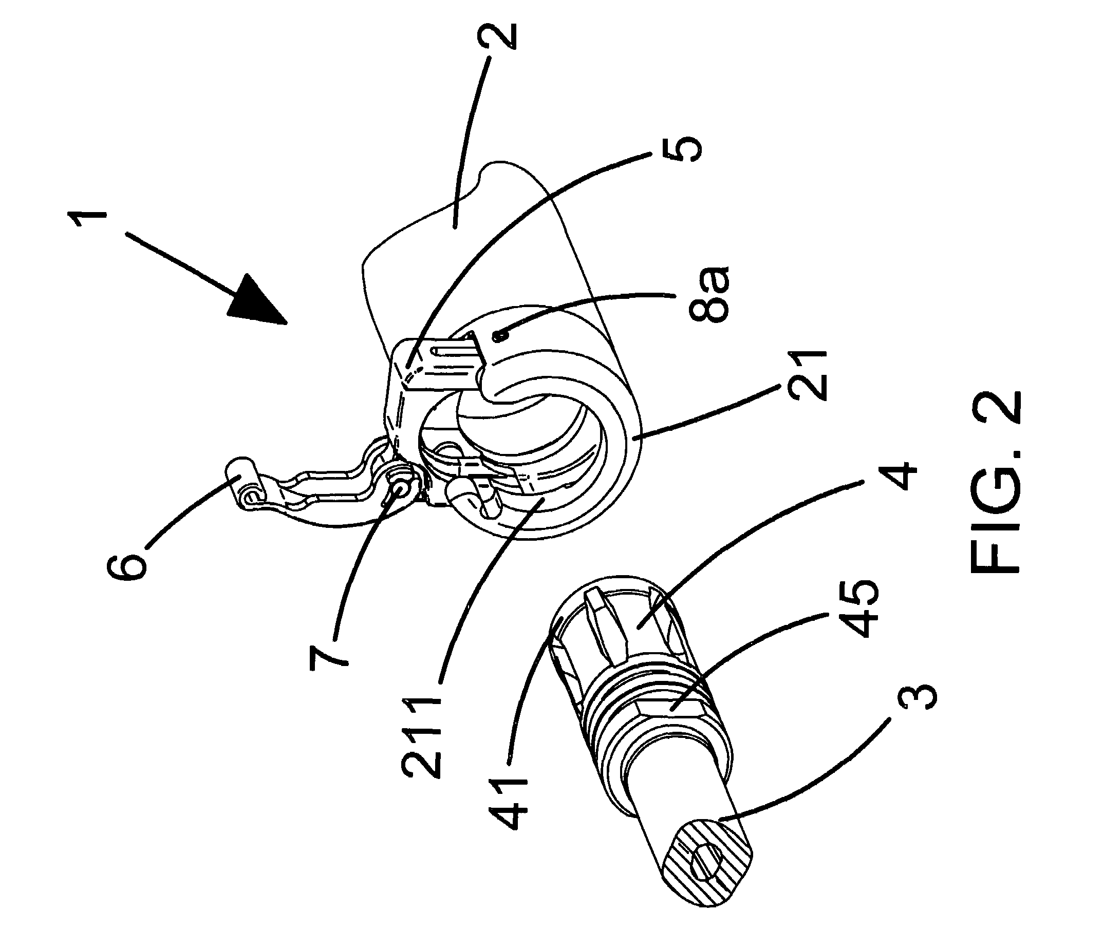
[0033]Referring in detail to FIG. 2 of the drawings, when secondary latch 6 has been rotated approximately ninety degrees about pivot pin 7, primary latch plate 5 can be lifted until latch retaining pins 8a and 8b (see FIG. 3) stops its travel. In this position flash hider 4 can be withdrawn from or seated into suppressor body assembly 2. Rear support 21 of suppressor body assembly 2 contains bore 211 which is of a size to accept outside diameter 41 of flash hider 4. Wrench flat 45 on flash hider 4 is intended to be mounted vertically in relation to the firearm upon which it is m...


PUM


Abstract

A latch for mounting a suppressor to a firearm is disclosed that allows interfacing with and securely attaching to the weapon's flash hider without the need to use threads and the rotational movement commonly associated with attaching suppressors to a firearm. The latch consists of a primary latch and a secondary latch. The primary latch moves in a vertical plane, fits into the grooves on a standard flash hider, and is rotationally indexed to the flash hider when locked. The secondary latch attaches to the top of the primary latch, securing the primary latch when it is fully locked by pivoting around and downwards, and locking to the suppressor. The primary latch compensates for the considerable tolerance range of the outside diameter of the flash hider. The latch has minimal thermal coupling to the suppressor and engaging/disengaging the primary latch plate and the secondary latch can be accomplished with one hand.

Description

BACKGROUND OF THE INVENTION[0001]1. Field of the Invention[0002]This application relates broadly to mounting systems for sound suppressors for firearms. More particularly, it concerns an improved latch system for sound suppressors for use with M4 Series Carbines, M16 Series rifles and other military and commercial automatic, semi-automatic and bolt action firearms.[0003]2. Description of the Prior Art[0004]The M4 Series Carbine and the M16 Series Rifles all use a common flash hider that has some considerable tolerance range for its outside diameter. This tolerance is a major factor in ensuring proper alignment occurs with the bore thru the suppressor baffles and the actual path of the projectile as it travels thru this bore when a sound suppressor is attached to the flash hider by various means. As a result of this tolerance factor, the bore hole through the suppressor usually has to be enlarged when compared to a suppressor using a screw thread attachment method or a proprietary fl...

Claims


Application Information

Patent Timeline
Patent Type & Authority Patents(United States)
IPC IPC(8): F41A21/30
CPCF41A21/325
Inventor OLSON, DOUGLAS D.
Owner WILSONS GUN SHOP
Why Eureka
Try Eureka