Surgical stapling instrument

a technology of surgical stapling and retaining pin, which is applied in the direction of surgical staples, manufacturing tools, mechanical equipment, etc., can solve the problems of less rigidity, misalignment of the ends of the staples and the staple forming face of the anvil, and the retaining pin of the staple leaves a hole in the tissu

Active Publication Date: 2010-06-15
CILAG GMBH INT
View PDF4 Cites 298 Cited by
  • Summary
  • Abstract
  • Description
  • Claims
  • Application Information

AI Technical Summary

Benefits of technology

[0014]In an advantageous version of the invention, the staple fastening assembly is adapted to allow unobstructed access towards concave inner faces of the cartridge device and of the anvil. Such design, which is generally known from WO 01 / 91646 A1, largely facilitates the handling of the stapling instrument in a surgical procedure.
[0018]In an advantageous version of the surgical stapling instrument, the cartridge device comprises a replaceable cartridge containing staples. In this way, a used cartridge without staples can be replaced with a fresh one, if required. This is particularly beneficial when the instrument is to be used several times during the same surgical procedure.
[0019]Some of the features discussed above are already known from WO 01 / 91646 A1, in particular an arc-like shape of the cartridge device and the anvil and a support arm extending from an end of the anvil, which enables an easy access to the site of surgery, e.g., for endoscopic optics or additional surgical instruments. The retaining pin of the present invention allows for a greater precision of the surgery without involving the risk of injury to tissue that may not be removed from the patient in the form of a specimen.

Problems solved by technology

Thus, under load when the tissue to be resected is clamped, the anvil might distort, leading to a misalignment of the ends of the staples and the staple forming face of the anvil.
For small surgical stapling instruments designed to be inserted through a small-diameter channel, this is a particular problem as there is not space enough for a sufficiently dimensioned, strong support arm at the end of the anvil.
The problem of current stapling instruments with a retaining pin at the free end of the cartridge device is that their retaining pin leaves a hole in the tissue outside the excision line defined by the knife length.
This kind of support allows for a large unobstructed area between the cartridge device and the anvil but has the general disadvantage that it is less rigid than, e.g., a design using a support arm in the center of the cartridge device and the anvil or using more than one support arm.
However, this disadvantage is compensated by the presence of the retaining pin by means of which the cartridge device and the anvil are aligned during the steps of the procedure when an alignment is critical, i.e. in particular when the cartridge device and the anvil are moved toward one another to force the tissue to compress to a thickness such to be stapled across and when the staples are then “fired” from the cartridge device and are formed by grooves in the staple forming face of the anvil.

Method used


Image

  • Surgical stapling instrument
  • Surgical stapling instrument
  • Surgical stapling instrument

Examples


Embodiment Construction

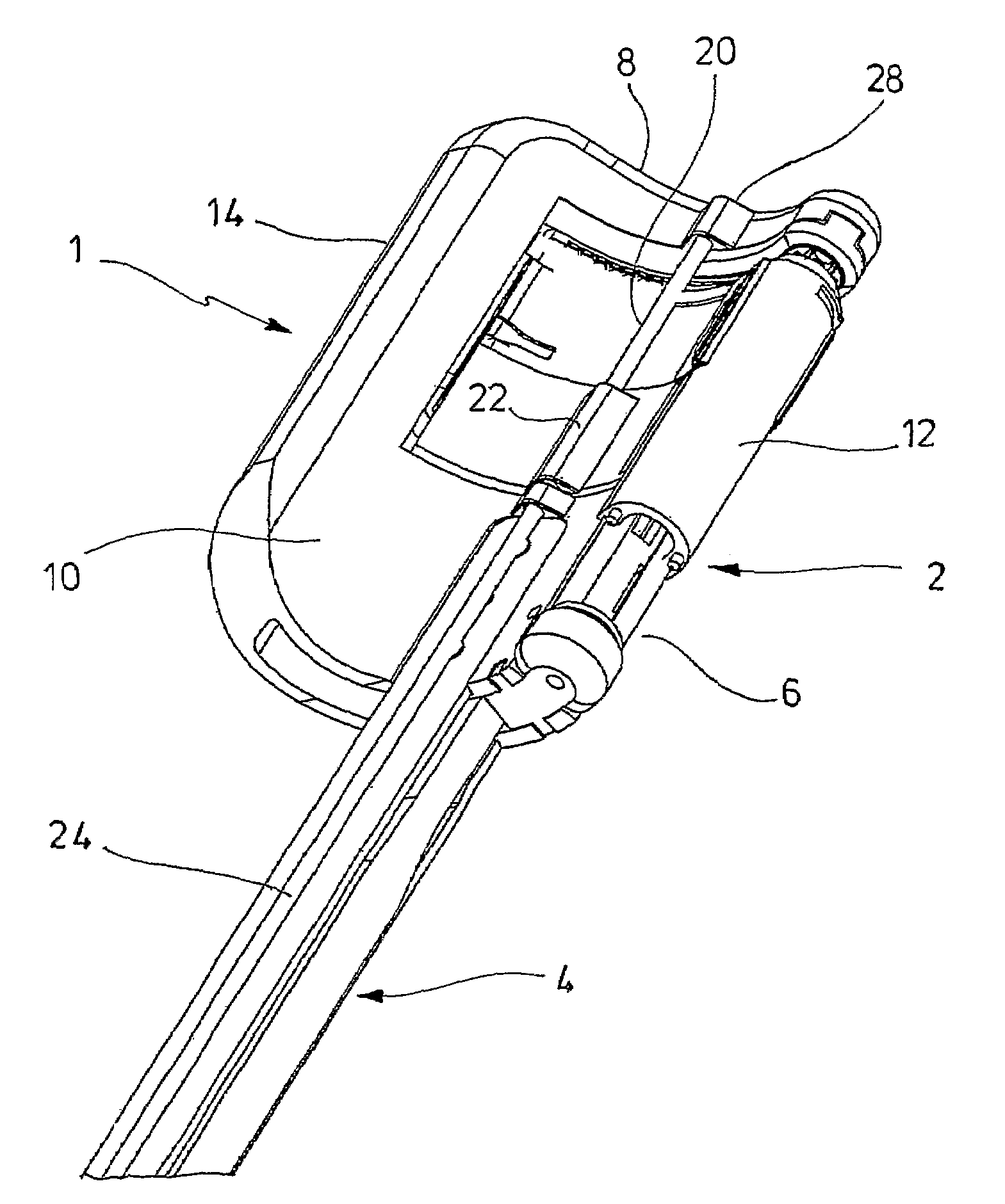
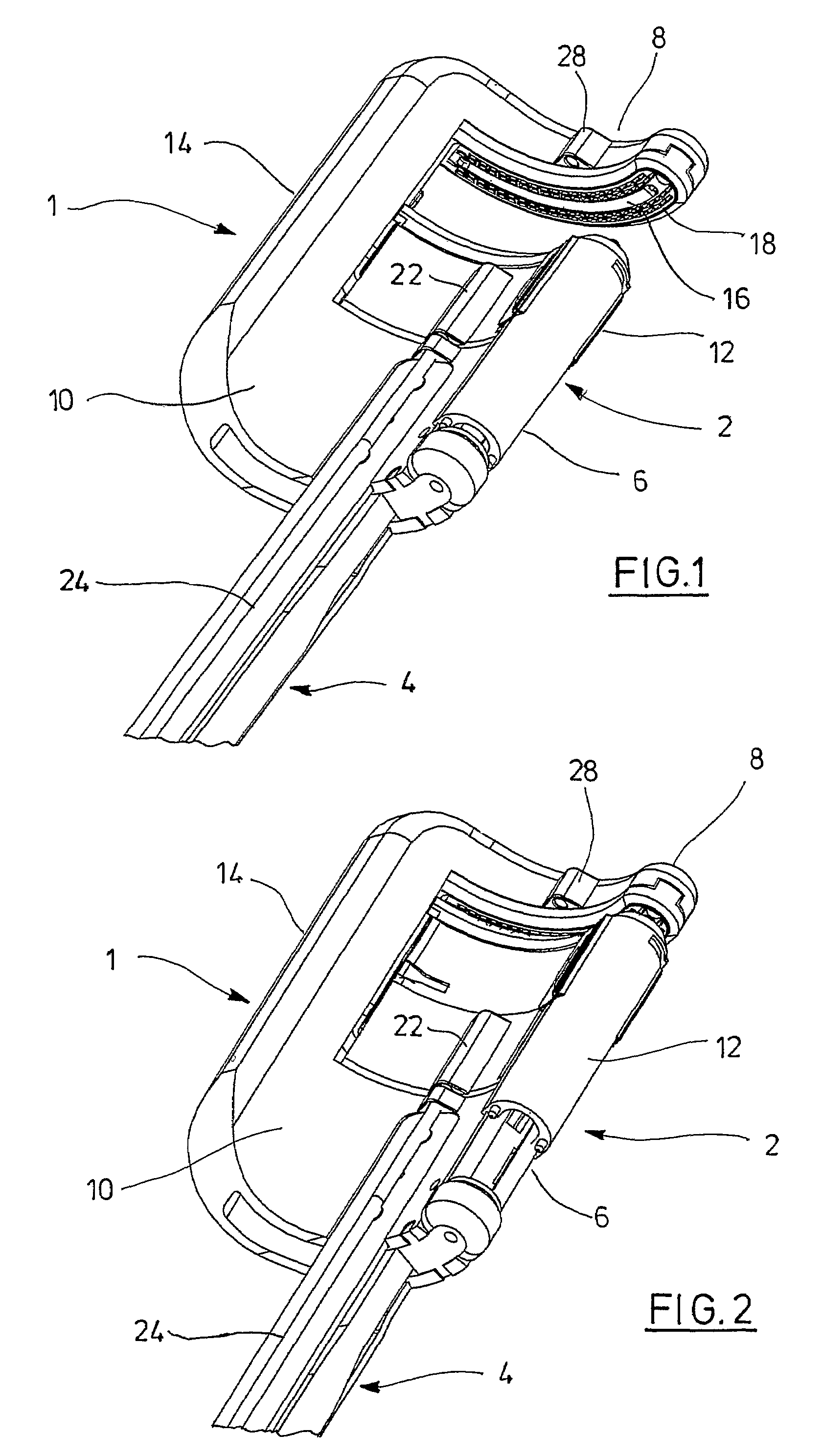
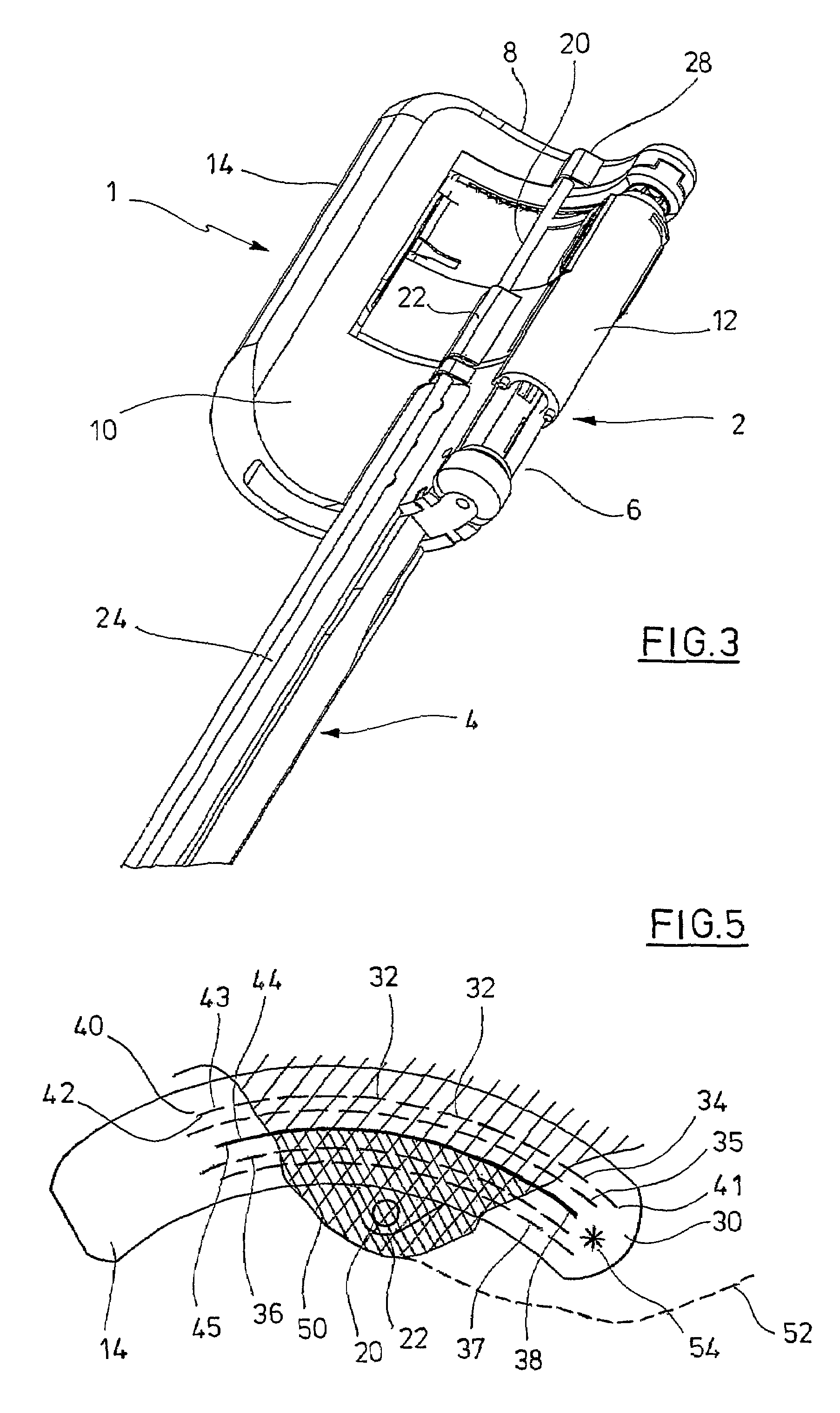
[0028]The surgical stapling instrument of the embodiment, which is designated by the reference numeral 1, has a similar design as the surgical stapling instrument described in detail in WO 01 / 91646A1. In addition to that instrument, however, the stapling instrument 1 includes a retaining pin in order to align the cartridge device and the anvil, as explained below.

[0029]The stapling instrument 1 comprises a staple fastening assembly 2 which is mounted at the distal end of a shaft 4. FIGS. 1 to 4 show the distal portion of shaft 4 only. In its proximal region, shaft 4 is attached to a handle having actuating members for operating the functions of the stapling instrument 1, as is known in the art. Force transmitting elements for transmitting the movements of the actuating members to the movable parts of the staple fastening assembly 2 are guided inside shaft 4 or in channels located at the surface of shaft 4. In the present embodiment, the staple fastening assembly 2 is fixed at the di...


PUM

PropertyMeasurementUnit
angleaaaaaaaaaa
angleaaaaaaaaaa
movementaaaaaaaaaa

Abstract

A surgical stapling instrument having a staple fastening assembly including a curved cartridge device. The device has at least one curved open row of staples having a first and second ends and having a concave side and a convex side. Opposite to the cartridge device there is a curved anvil for forming the ends of the staples. The instrument also includes a moving device adapted to move the anvil with respect to the cartridge device in a parallel relationship. The instrument also includes a staple driving device adapted to drive the staples out of the cartridge device towards the anvil, and a knife. The knife has opposing first and second sides and is contained in the cartridge device. There is also a knife actuating device adapted to move the knife towards the anvil. The instrument includes staple fastening assembly having a retaining pin which moves between the cartridge device to align them. The retaining pin is located on the second side of the knife in an intermediate region between the first end and second ends of the curved row of staples.

Description

FIELD OF THE INVENTION[0001]The invention relates to a surgical stapling instrument, which can be used, e.g., in the diagnosis and therapy of all pathologies treated by a curved stapled resection.BACKGROUND OF THE INVENTION[0002]Such a surgical stapling instrument is known from WO 01 / 91646 A1. WO 01 / 91646 A1 discloses a surgical stapling instrument having a staple fastening assembly located in the distal end region of the stapling instrument, a shaft, and a handle extending from the shaft in the proximal end region of the stapling instrument. The staple fastening assembly includes a curved cartridge device, which comprises several curved open rows of staples having a concave side and a convex side. A curved anvil is arranged opposite to the cartridge device. The anvil has a staple forming face and is adapted to cooperate with the cartridge device for forming the ends of the staples exiting from the cartridge device. The anvil can be moved relatively with respect to the cartridge dev...

Claims


Application Information

Patent Timeline
Patent Type & Authority Patents(United States)
IPC IPC(8): A61B17/064A61B17/072
CPCA61B17/072A61B2017/0725A61B2017/07221A61B2017/07214
Inventor BILOTTI, FEDERICO
Owner CILAG GMBH INT
Why Eureka
Try Eureka