Pluggable connector with differential pairs

a technology of differential pairs and pluggable connectors, which is applied in the direction of coupling devices, connection contact materials, two-part coupling devices, etc., can solve the problems of affecting the integrity of signal integrity and the performance of connectors, unwanted electromagnetic coupling between differential pairs, and limitations of pluggable connectors currently used

Inactive Publication Date: 2010-06-15
TE CONNECTIVITY CORP
View PDF15 Cites 34 Cited by
  • Summary
  • Abstract
  • Description
  • Claims
  • Application Information

AI Technical Summary

Benefits of technology

[0007]Optionally, the grounding member has a cross-section taken perpendicular to the central axis. The cross-section of the grounding member may have a thickness that decreases as the grounding member extends toward the central axis. ...

Problems solved by technology

However, pluggable connectors that are currently used may have certain limitations due to unwanted electromagnetic coupling between the differential pairs.
For example, the operating speeds of M-series pluggable connectors are limited to transmission rates of less than one gigabit per second.
If current M-series pluggable connectors...

Method used


Image

  • Pluggable connector with differential pairs
  • Pluggable connector with differential pairs
  • Pluggable connector with differential pairs

Examples


Embodiment Construction

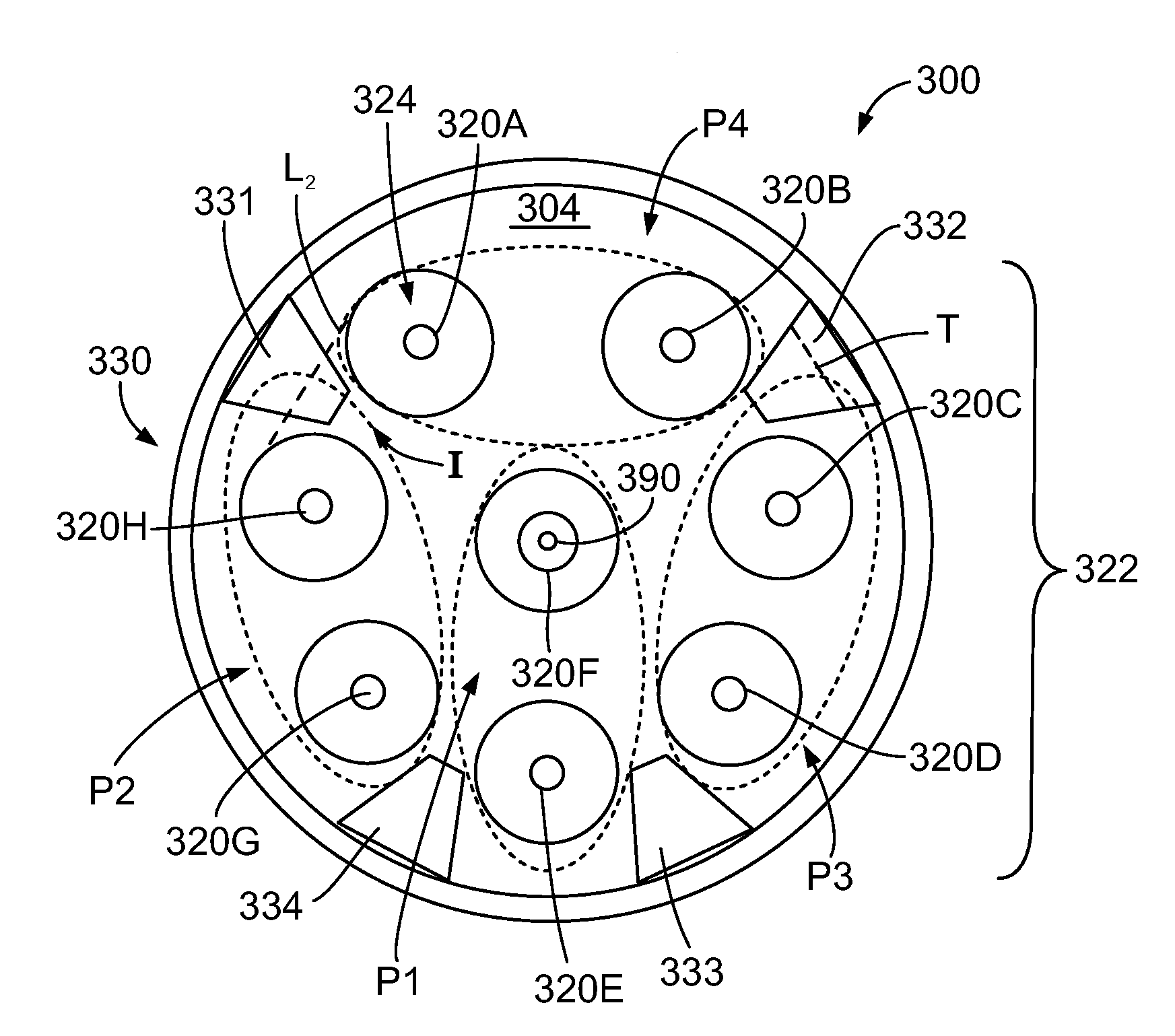
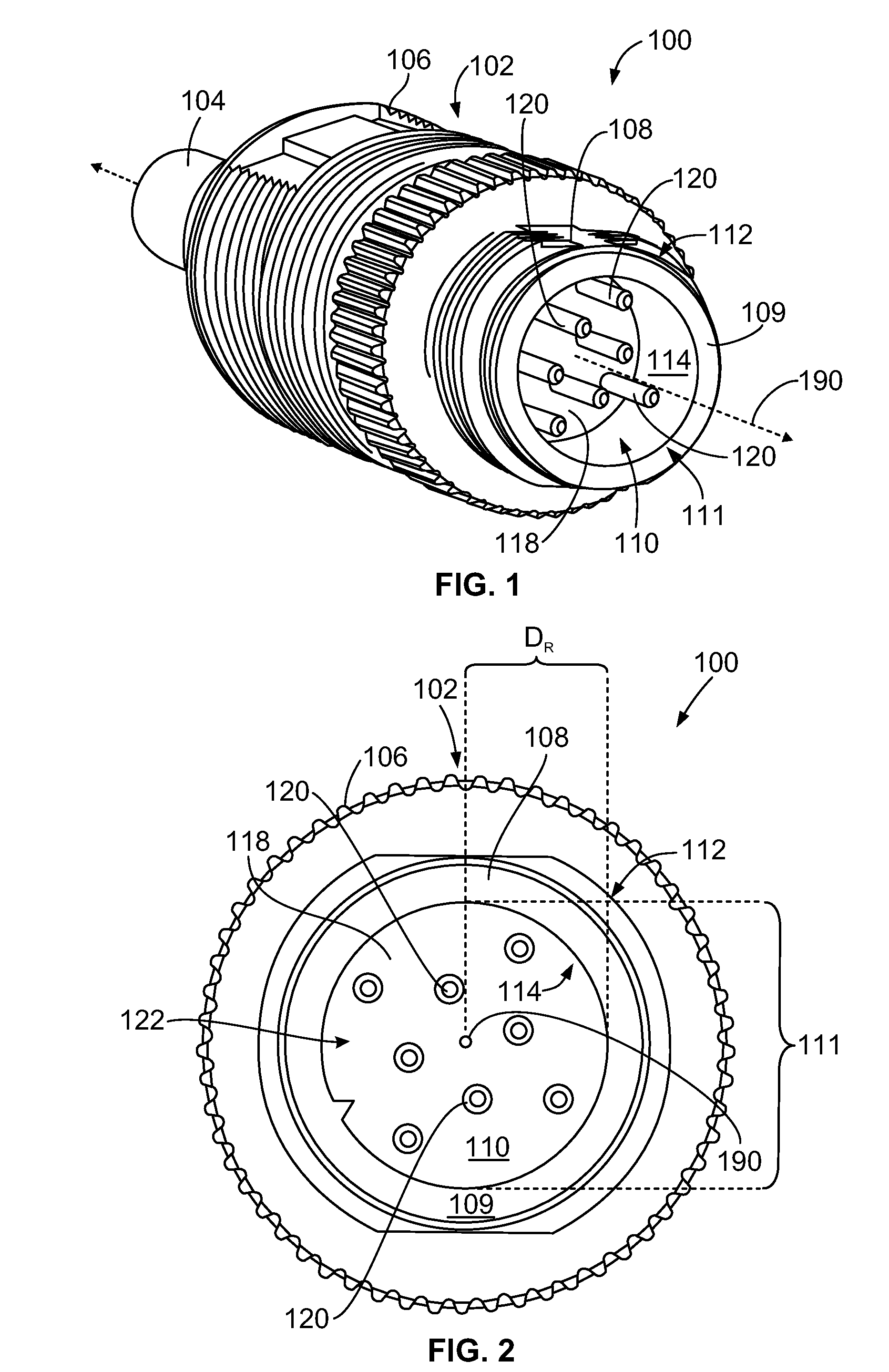
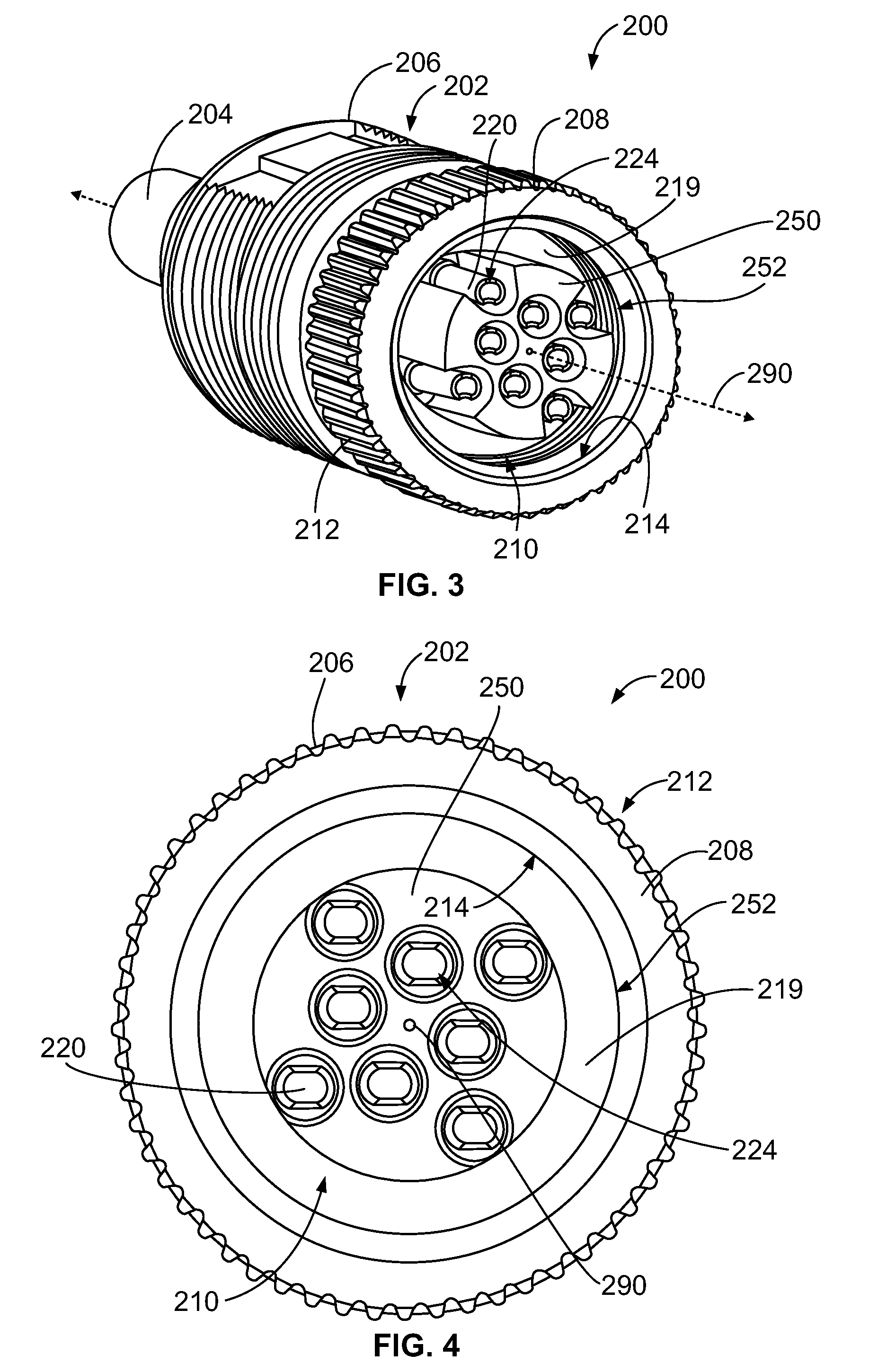
[0018]Embodiments described herein include pluggable connectors having mating contacts that form differential pairs. The differential pairs may be arranged to improve the performance of pluggable connectors with respect to other known connectors. For example, embodiments described herein have differential pairs arranged to reduce, control, or improve upon at least one of insertion loss, near-end crosstalk (NEXT), far-end crosstalk, and return loss. Alternatively or additionally, the pluggable connector may include grounding members that extend alongside and between mating contacts and are configured to isolate the differential pairs. A “pluggable connector.” as described herein, is an electrical connector that is configured to mate with another electrical connector (also referred to as a mating connector) through a pluggable engagement. For example, pluggable connectors described herein include plug connectors that have a plug insert configured to be inserted into a cavity of a mati...


PUM


Abstract

A pluggable connector that includes a housing having an inner surface that defines a housing cavity. The housing cavity extends along a central axis to an opening of the housing cavity. The opening is sized and shaped to mate with a mating connector moving along the central axis. The connector also includes a plug insert that is positioned within the housing cavity. The plug insert extends along the central axis and forms contact cavities therein that extend parallel to the central axis. The plug insert has an outer surface that is separated from the inner surface of the housing by a spacing. The connector also includes differential pairs. Each differential pair has two mating contacts that extend parallel to each other along a contact plane of the differential pair and within corresponding contact cavities. The contact planes of at least two adjacent differential pairs are perpendicular to one another.

Description

BACKGROUND OF THE INVENTION[0001]The invention relates generally to connectors, and more particularly to pluggable connectors for high-speed transmission.[0002]Electrical connectors used to plug a communication cable into an electrical system may include a housing that contains several conductors that form differential pairs. The differential pairs are configured to connect with corresponding differential pairs in a mating connector of the electrical system (e.g. a port) when the pluggable and mating connectors are engaged. However, pluggable connectors that are currently used may have certain limitations due to unwanted electromagnetic coupling between the differential pairs. For example, the operating speeds of M-series pluggable connectors are limited to transmission rates of less than one gigabit per second. If current M-series pluggable connectors were to operate at speeds above one gigabit / s, the unwanted electromagnetic coupling between the differential pairs would harm signa...

Claims


Application Information

Patent Timeline
IPC IPC(8): H01R13/648H01R13/6467H01R13/658
CPCH01R24/86H01R13/6471H01R13/6585
Inventor EFFINGER, III, ROBERT PETERSHANBHAG, MEGHAWILLIAMS, BRIAN
Owner TE CONNECTIVITY CORP
Why Eureka
Try Eureka