Imaging device, lens drive control method and recording medium

a technology of lens drive and control method, which is applied in the direction of printers, instruments, cameras focusing arrangement, etc., can solve the problems of reducing the miniaturization of the camera unit, affecting the quality of the image, so as to reduce the shifting of the zoom magnification and focus, and save space

Active Publication Date: 2010-06-15
LENOVO INNOVATIONS LTD HONG KONG
View PDF18 Cites 2 Cited by
  • Summary
  • Abstract
  • Description
  • Claims
  • Application Information

AI Technical Summary

Benefits of technology

[0023]According to the invention, a voltage generated when an external shock is applied to the piezoelectric element is detected, and when it is determined that the detected voltage is larger than or equal to a value, it is possible to set the lens at the original position again. This suppresses shifting of a zoom magnification and focus caused by positional misalignment of the lens. By using the same piezoelectric element for lens driving and for external shock detection, it is possible to save a space.

Problems solved by technology

The use of a step motor limits the miniaturization of a camera unit.
Shooting in this state raises problems such that a zoom magnification differs from one desired by a user and a focus is missed.
Such problems may be overcome by providing some mechanism for fixing a lens at the correct position, which would enlarge the lens drive device and complicate control of lock / release of the lens.
Those problems are not limited to a camera-mounted cellular phone, and also arise in an optical system using the vibration type actuator.

Method used


Image

  • Imaging device, lens drive control method and recording medium
  • Imaging device, lens drive control method and recording medium
  • Imaging device, lens drive control method and recording medium

Examples


first embodiment

[0038]Best modes for carrying out the invention will be explained in detail.

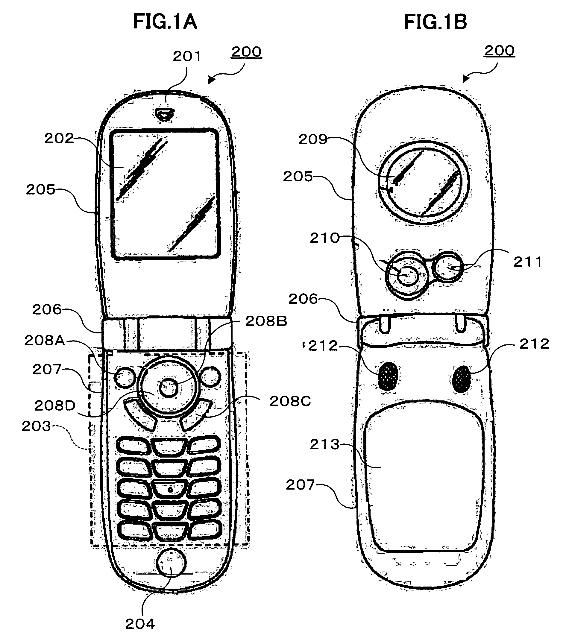
[0039]FIGS. 1A and 1B are external views illustrating a camera-mounted cellular phone 200 having a lens control device according to the first embodiment of the invention. FIG. 1A illustrates the front external appearance of the cellular phone 200 with a lid 205 thereof opened, and FIG. 1B illustrates the rear external appearance with the lid 205 opened.

[0040]As illustrated in the figures, the cellular phone 200 is structured in such a way that a hinge unit 206 couples the lid 205 and a main body 207, and is foldable.

[0041]Like general cellular phones, the cellular phone 200 has a speaker 201 for communication, a main display unit 202, a key input unit 203, a microphone 204 for communication, a sub display unit 209, a camera unit 210, a stroboscope LED (Light Emitting Diode) 211, a stereo speaker 212, a rechargeable battery 213, and the like.

[0042]The key input unit 203 has, for example, a camera key 208A for...

second embodiment

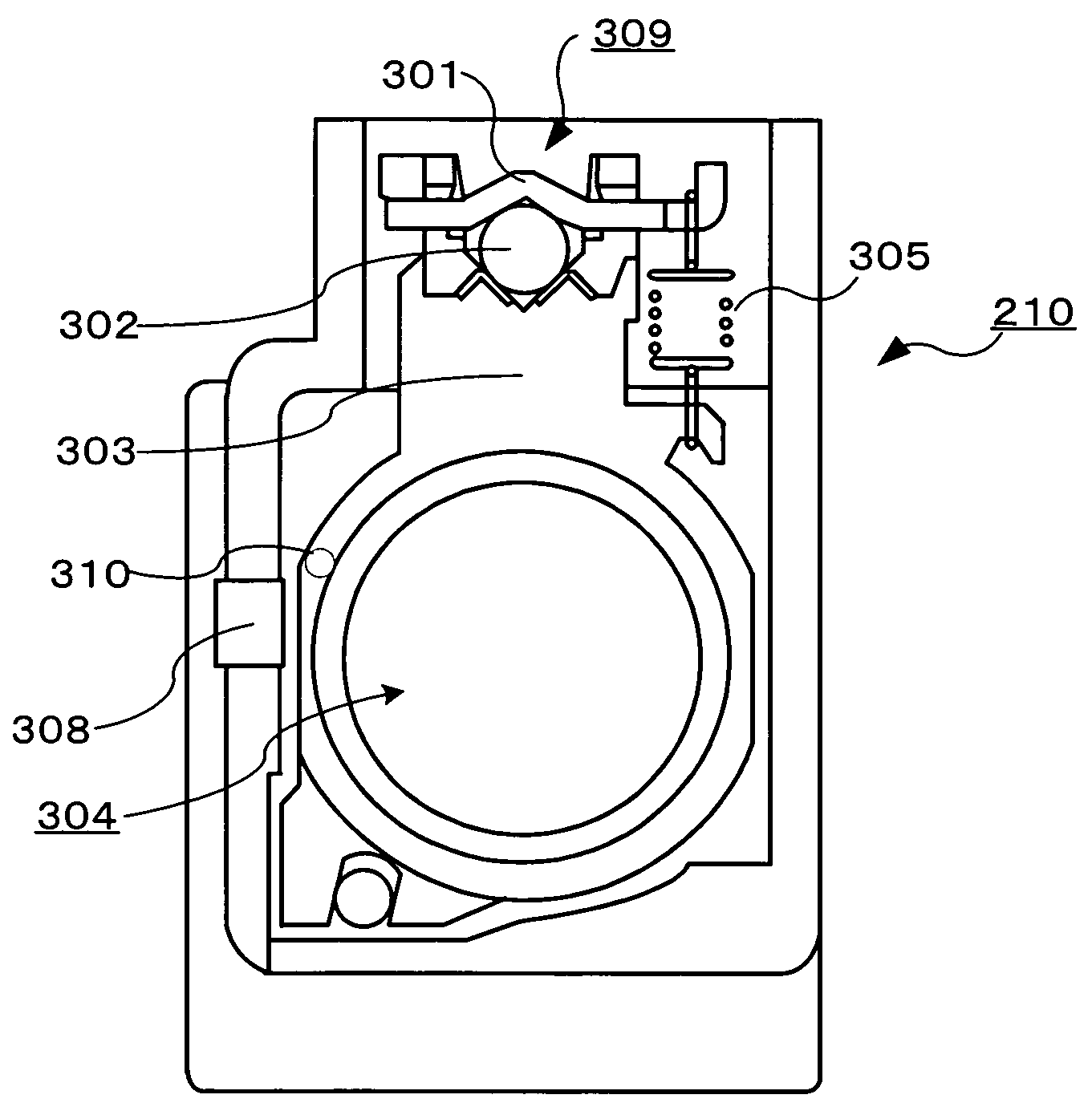
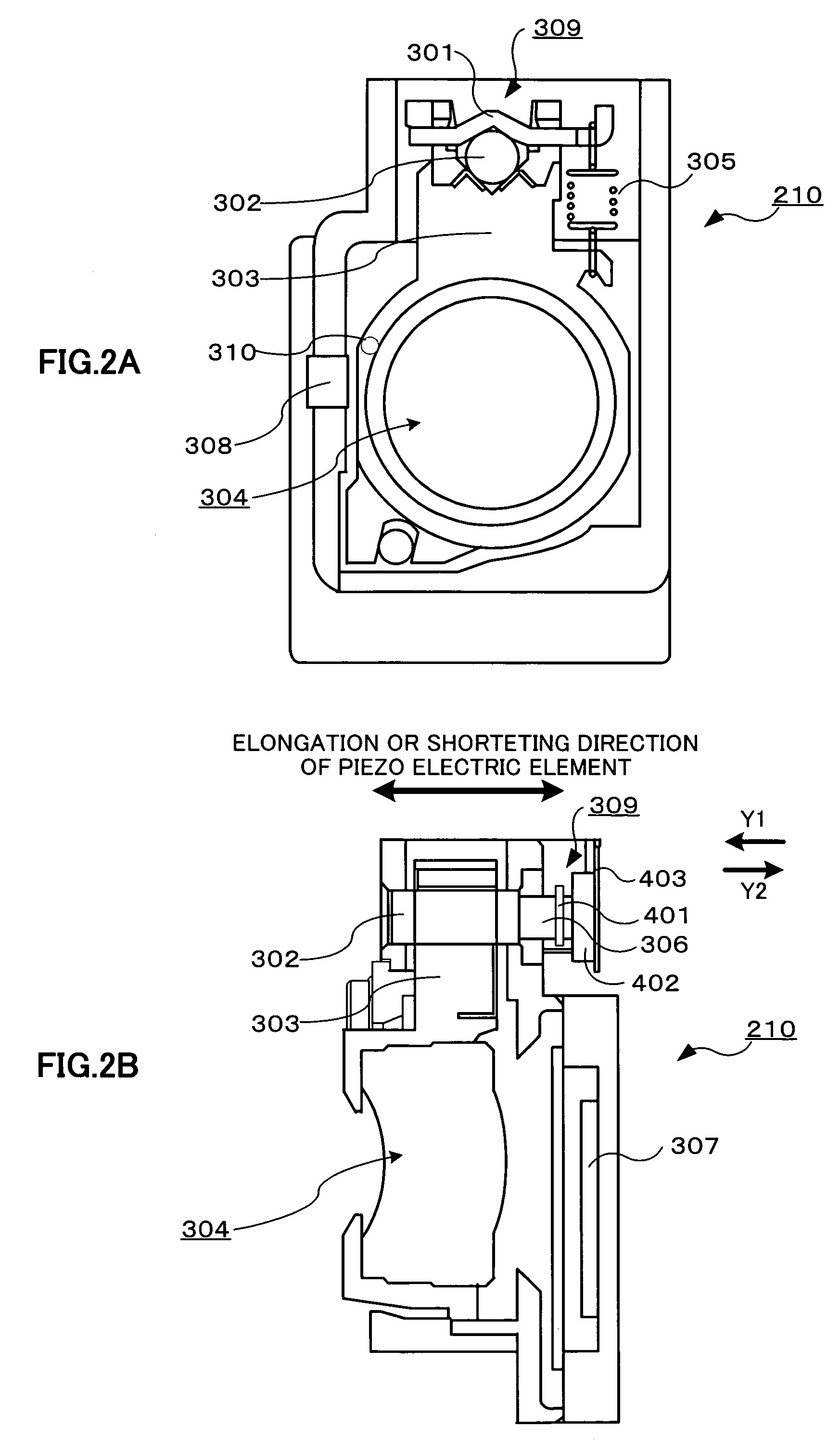
[0088]The first embodiment explains the camera unit 210 structured in such a way that the depth of field of the lens 304 is deep and the object is always focused within the movable range of the lens 304, but the invention can be applied to a further high performance camera unit. For example, the invention can be applied to a camera unit which can separately adjust a zoom and a focus.

[0089]In this embodiment, a plurality of lenses 304 each of which can adjust the position thereof are disposed at the position of the lens 304 illustrated in FIG. 2. A vibration actuator and a drive circuit are disposed with respect to each lens, and the position of each lens 304 is detected. By disposing the vibration type actuator and the drive circuit with respect to each lens 304, it is possible to separately control changing of a zoom magnification and adjustment of a focus. Accordingly, as the depth of field of the lenses 304 may not be deep, the camera of the cellular phone 200 can shoot a further...

third embodiment

[0098]Next, the other embodiment of the invention will be explained. In the embodiment, the cellular phone 200 can detect a vibration and a shock originating from opening / closing of the lid 205, and adjust the position of the lens 304. As illustrated in FIG. 9, an opening / closing detection magnet 501 and an opening / closing detection Hall element 502 are respectively embedded in the lid 205, and the main body 207, of the cellular phone 200. A distance between the opening / closing detection magnet 501 and the opening / closing Hall element 502 varies in accordance with opening / closing of the lid 205. A magnetic field intensity detected by the opening / closing detection Hall element 502 changes in accordance with the change of the distance. The controller 108 determines the opened / closed state of the lid 205 of the cellular phone 200 from an output voltage of the opening / closing detection Hall element 502. The cellular phone 200 can image an object by the camera unit 210 with the lid 205 o...


PUM


Abstract

A controller controls a drive waveform generator to apply a predetermined voltage to a piezoelectric element and deform the piezoelectric element, thereby moving a lens. The controller acquires the position of the lens based on a magnetic field intensity detected by a Hall device. A shock detection circuit measures a voltage generated by deformation of the piezoelectric element caused by an external shock. The controller determines whether or not the voltage measured by the shock detection circuit is larger than a predetermined threshold, and detects positional misalignment of the lens. When detecting the positional misalignment, the controller resets the lens at a position acquired before the shock was applied.

Description

BACKGROUND OF THE INVENTION[0001]1. Field of the Invention[0002]The present invention relates to an imaging device, a lens drive control method and a recording medium.[0003]2. Description of the Related Art[0004]Conventionally, user's manipulation of an external lever or the like changes over the image magnification powers and focal distances of a camera-mounted cellular phone and a camera unit for which miniaturization and flattening are demanded. There is a camera unit which has a downsized step motor and an AF (Auto Focus) function of moving an imaging lens by the step motor.[0005]The use of a step motor limits the miniaturization of a camera unit. In place of this type of camera unit, recent camera units have a piezoelectric element (piezo element) which is used to move a lens. Using the piezoelectric element makes it possible to further lighten and miniaturize the camera units. Piezoelectric elements have a deformation characteristic in accordance with an applied voltage. A cam...

Claims


Application Information

Patent Timeline
Patent Type & Authority Patents(United States)
IPC IPC(8): G02B7/02
CPCG02B7/023G02B7/04G03B3/10G03B13/34G03B17/12G03B30/00G03B2205/0061
Inventor TOMITA, SHIGEAKI
Owner LENOVO INNOVATIONS LTD HONG KONG
Why Eureka
Try Eureka