X-ray focusing optic having multiple layers with respective crystal orientations

a technology of focusing optics and crystal orientations, applied in the field of xray optics, can solve the problems of only having the option of producing high-intensity x-ray beams, anode x-ray tubes, synchrotrons,

Active Publication Date: 2010-06-15
X-RAY OPTICAL SYSTEM INC
View PDF5 Cites 52 Cited by
  • Summary
  • Abstract
  • Description
  • Claims
  • Application Information

AI Technical Summary

Benefits of technology

[0006]The shortcomings of the prior art are overcome and additional advantages are provided by the present invention, which in one aspect is an optic for accepting and redirecting x-rays, the optic having at least two layers, the layers having a similar or differing material composition and similar or differing crystalline orientation. Each of the layers exhibits a diffractive effect, and their collective effect provides a diffractive effect on the received x-rays. In one embodiment, the layers are silicon, and are bonded together using a silicon-on-insulator bonding technique. In another embodiment, an adhesive bonding technique may be used. The optic may be a curved, monochromating optic.

Problems solved by technology

In the past, expensive and powerful x-ray sources, such as rotating anode x-ray tubes or synchrotrons, were the only options available to produce high-intensity x-ray beams.

Method used


Image

  • X-ray focusing optic having multiple layers with respective crystal orientations
  • X-ray focusing optic having multiple layers with respective crystal orientations
  • X-ray focusing optic having multiple layers with respective crystal orientations

Examples


Embodiment Construction

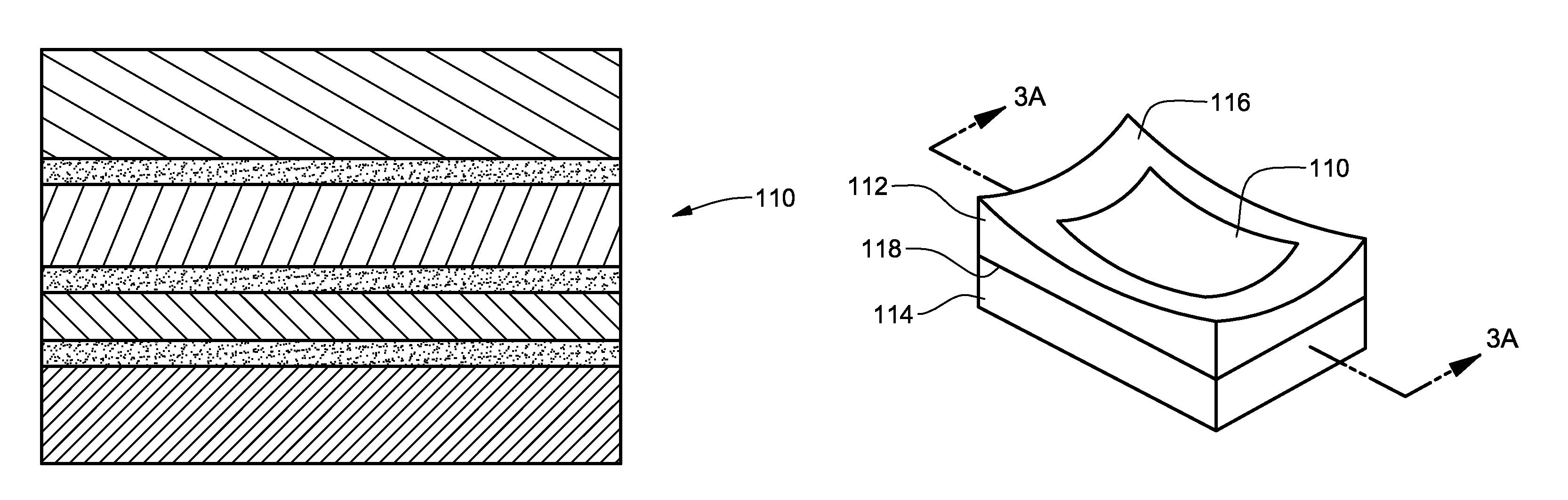
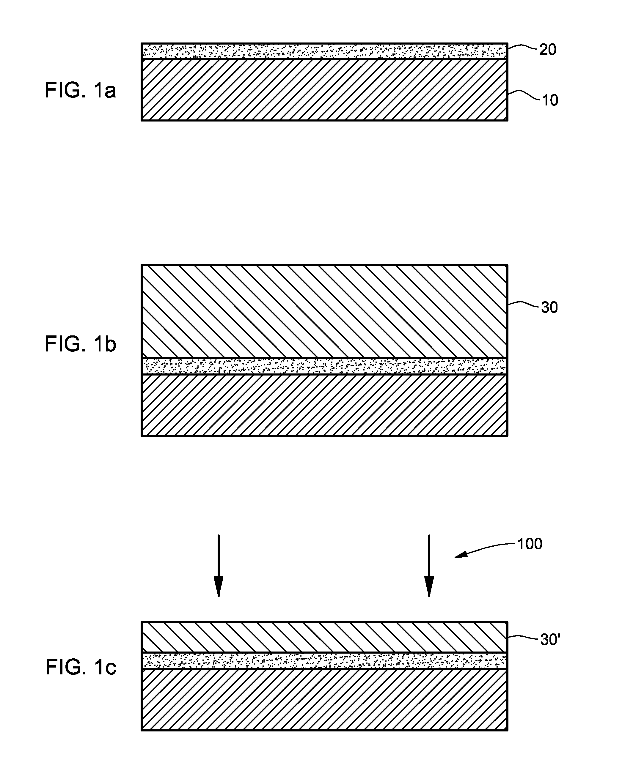
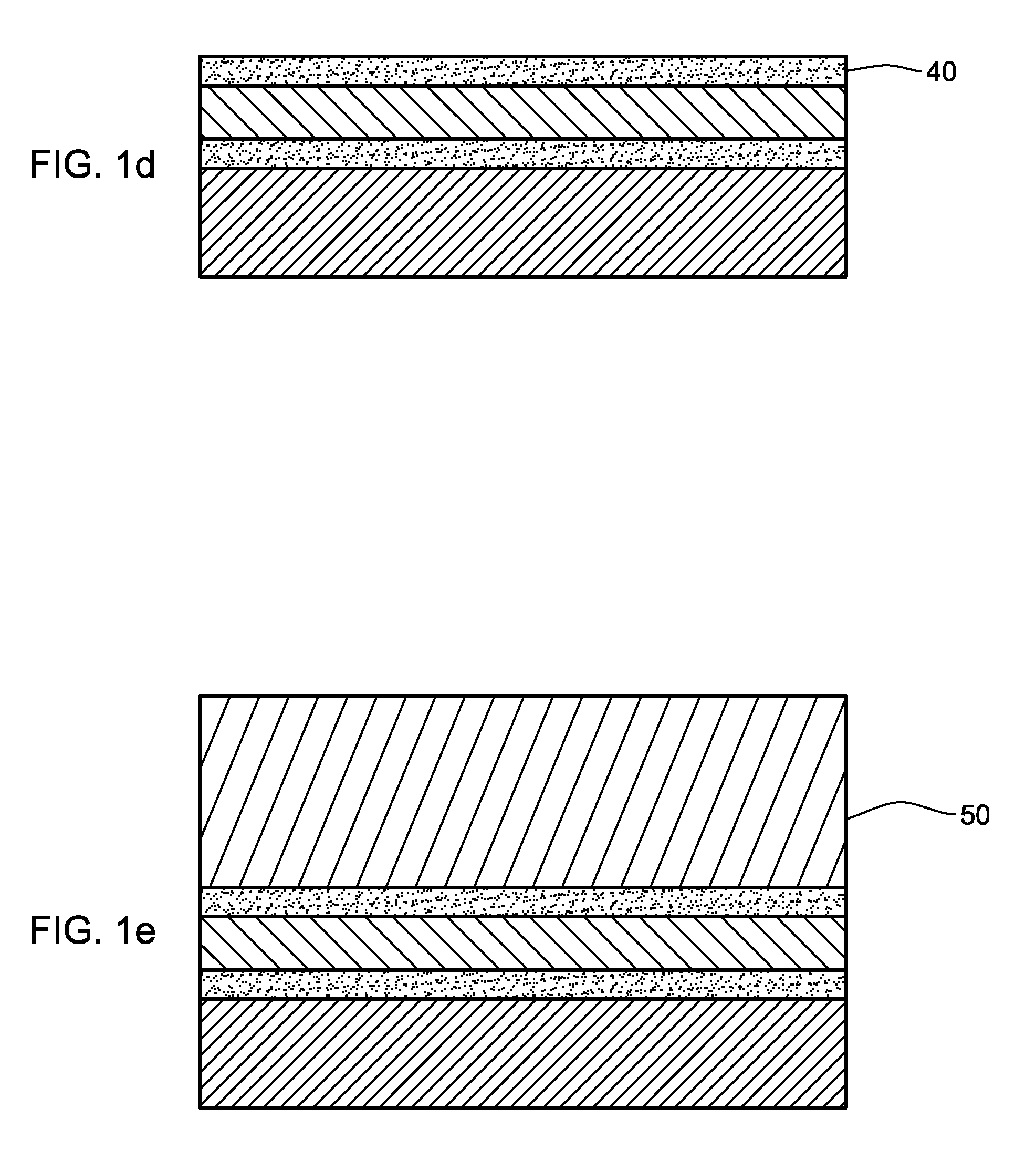
[0015]An x-ray optic structure and exemplary technique for its formation are disclosed with reference to FIGS. 1a-i. (The dimensions in these drawings are exaggerated, and not necessarily in proportion, for illustrative purposes only.) As discussed further below, the optic formed according to the present invention includes multiple layers of, e.g., silicon, each layer having a different, pre-determined crystalline orientation, and bonded together using, e.g., a silicon-on-insulator bonding technique.

[0016]Silicon-on-insulator (SOI) bonding techniques are known in the art, as described in Celler et al, “Frontiers of Silicon-on-Insulator,” Journal of Applied Physics, Volume 93, Number 9, 1 May 2003, the entirety of which is incorporated by reference. In general, SOI techniques involve molecular bonding at the atomic / molecular level using, e.g., Van der Walls forces, and possibly chemically assisted bonding. The term “material-on-insulator” is used broadly herein to connote this family...


PUM

PropertyMeasurementUnit
thicknessesaaaaaaaaaa
thicknessaaaaaaaaaa
thicknessaaaaaaaaaa

Abstract

A diffracting x-ray optic for accepting and redirecting x-rays. The optic includes at least two layers, the layers having a similar or differing material composition and similar or differing crystalline orientation. Each of the layers exhibits a diffractive effect, and their collective effect provides a diffractive effect on the received x-rays. In one embodiment, the layers are silicon, and are bonded together using a silicon-on-insulator bonding technique. In another embodiment, an adhesive bonding technique may be used. The optic may be a curved, monochromating optic.

Description

CROSS-REFERENCE TO RELATED APPLICATIONS[0001]This application claims the benefit of U.S. Provisional Application No. 60 / 866,134, filed Nov. 16, 2006. This Provisional Application is hereby incorporated herein by reference in its entirety.TECHNICAL FIELD[0002]This invention relates in general to x-ray optics, and in particular to an improved x-ray focusing crystal optic having multiple layers, each layer having a predetermined crystalline orientation.BACKGROUND OF THE INVENTION[0003]In x-ray analysis systems, high x-ray beam intensity and small beam spot sizes are important to reduce sample exposure times, increase spatial resolution, and consequently, improve the signal-to-background ratio and overall quality of x-ray analysis measurements. In the past, expensive and powerful x-ray sources, such as rotating anode x-ray tubes or synchrotrons, were the only options available to produce high-intensity x-ray beams. Recently, the development of x-ray optic devices has made it possible to...

Claims


Application Information

Patent Timeline
Patent Type & Authority Patents(United States)
IPC IPC(8): G21K1/06
CPCG21K1/06G21K2201/064G21K2201/062
Inventor CHEN, ZEWU
Owner X-RAY OPTICAL SYSTEM INC
Why Eureka
Try Eureka