Clinch nut

a clinch nut and nut technology, applied in the field of self-attaching fasteners, can solve the problems of unsatisfactory or competitive, unwanted deformation or distortion of the fastener, and the hardness and strength of the clinch nut may not be simply increased to solve the foregoing problems, and achieves greater piercing and/or setting forces, increased strength of metal members, and enhanced fastener resistance

Active Publication Date: 2010-06-22
R B & W MFG
View PDF25 Cites 12 Cited by
  • Summary
  • Abstract
  • Description
  • Claims
  • Application Information

AI Technical Summary

Benefits of technology

[0009]It has now been found that selective hardening of metal portions of clinch fasteners enable their use with metal members of differing hardness values. The selective hardening of the fastener enables mounting with application of required forces for piercing and / or plastic deformation of the metal member without undesirable deformation or distortion of the fastener. Further, the fastener region in which screw threads are to be formed is provided with a relatively lesser hardness suitable for threading by engagement with a thread forming screw.
[0013]The clinch fastener is typically hardened along the axial length of the pilot portion to assure the latter has a sufficient compressive strength to pierce the metal member. The pilot portion has a generally cylindrical shape, and the hardening is provided in an outer zone adjacent the periphery of the pilot portion. In this manner, the outer zone is provided with a circular or cylindrical shape which is highly resistant to buckling and thereby further strengthens the pilot portion.
[0014]The annular bottom end of the body portion of the fastener surrounding the pilot portion may also be hardened to provide a bottom end zone having a hardness substantially equal to that of the outer zone. The hardened bottom zone cooperates with the outer zone to coin and deform the metal member into tight engagement with the fastener. Further, the hardening of the bottom zone enhances the security and mounting of the fastener to the metal member. The bottom zone may be provided with specially configured or shaped elements for better deforming and / or interlocking with plastically deformed metal.
[0017]In another embodiment of the invention, the top annular end face of the body portion of the fastener is also induction hardened to provide a top zone having a hardness greater than that of the inner zone and / or substantially equal to that of the outer zone. The top zone enhances the fastener's resistance to the relatively greater piercing and / or setting forces required to affix the fastener to the higher strength metal members.
[0018]In this further embodiment, the outer periphery of the body portion of the fastener may also be induction hardened to provide a peripheral zone having a hardness greater than that of the inner zone and / or substantially equal to that of the outer zone. The peripheral zone may extend along a portion of the axial extent of the outer periphery of the body portion to provide additional fastener strength.
[0019]In a further variation, the peripheral zone extends along the entire axial extent of the outer periphery of the body portion to connect the top zone and the bottom zone. This provides joined and substantially continuous zones of increased hardness about nearly the entire periphery or outer portions of the fastener. This further increases and enhances the fastener's resistance to the relatively greater piercing and / or setting forces required to affix the fastener to the higher strength metal members.

Problems solved by technology

Such increased piercing and setting forces may result in unwanted deformation or distortion of the fastener.
The hardness and strength of the clinch nut may not be simply increased to resolve the foregoing problems without loss of the manufacturing flexibility of thread forming by engagement with a self-threading screw.
It is not desirable or competitive to provide specialty self-threading screws useful with metals of differing higher hardness values and / or clinch nuts with a variety of hardness values for use with metal members of differing strength and hardness properties.

Method used


Image

  • Clinch nut
  • Clinch nut
  • Clinch nut

Examples


first embodiment

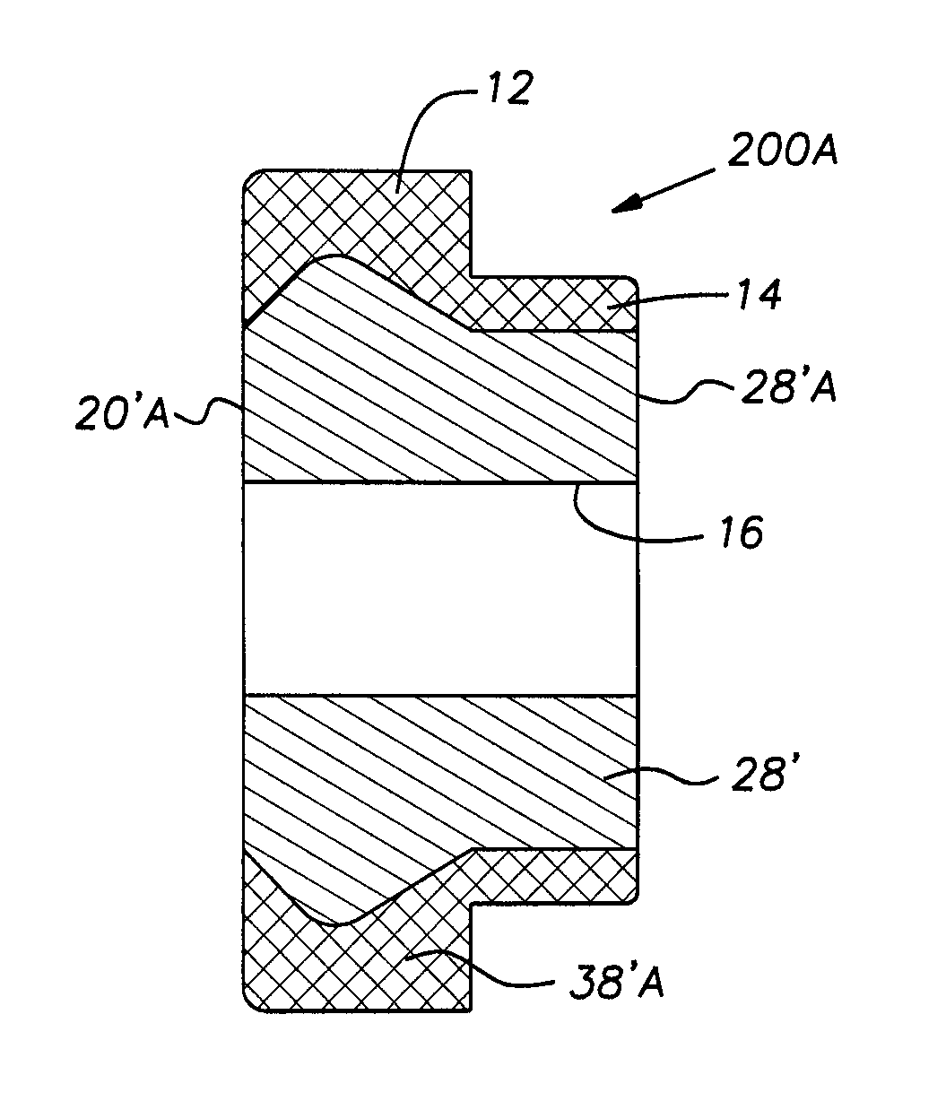
[0053]The self-piercing clinch nut 10′ has a body portion 12′ and a pilot or punch portion 14′ extending from one end of the body portion 12′. A thread blank or bore 16 extends along the longitudinal axis A of the nut 10′. As in the first embodiment, the body portion 12′ includes an annular mounting or bottom end face 18′, an annular top end face 20′ and a peripheral body face 22′ that joins the end face 18′ and the top face 20′.

[0054]In this embodiment, the annular top end face 20′ is also selectively hardened to provide a top zone 32 remote of the inner zone 28′. The top zone 32 has an annular shape extending transversely or radially outwardly along the end face 20′ from an annular top end face 20′A corresponding with the thread major diameter to the outer peripheral body face 22′.

[0055]The top zone 32 has a hardness corresponding with that of the outer zone 24′. The increased hardness of the top zone further resists crushing and / or plastic deformation of the metal forming the top...

second embodiment

[0062]As described in connection with the second embodiment, the nut 10″ may also be provided with a top zone 32 in its top face 20′. A peripheral zone 34 extends along the peripheral body face 22′. Again, the top zone 32 may extend to the dotted line 36 to form the enlarged peripheral zone 38 to substantially encase the nut 10″ in joined and continuous zones of increased metal hardness.

[0063]Clinch nuts having various pilot shapes, annular face arrangements and lugs are also illustrated in Design applications Nos. D440,865S, D448,659S and D448,660S. Selected figures from these design cases are included herein and briefly discussed below.

[0064]Referring to FIGS. 8 through 10, a nut 40 is shown. The nut 40 includes a body portion 42, a pilot portion 44 and a screw thread 46 extending along a central axis.

[0065]The nut 40 includes a mounting or bottom end face 48, an annular top end face 50 and a peripheral body face 52 joining the bottom and top faces. A generally annular shaped groo...


PUM

PropertyMeasurementUnit
ultimate tensile strengthaaaaaaaaaa

Abstract

A metal clinch fastener has portions thereof selectively hardened to enable use of the fastener with metal members of differing hardness values. The selective hardening of the fastener enables mounting with application of required forces for piercing and / or plastic deformation of the metal member without undesirable deformation or distortion of the fastener. The screw thread region or zone of the fastener has a relatively lesser hardness suitable and may be pre-threaded or later threaded by engagement with a thread forming screw.

Description

[0001]This application claims the priority of U.S. Provisional Application No. 60 / 784,878, filed Mar. 22, 2006.BACKGROUND OF THE INVENTION[0002]The present invention generally relates to self-attaching fasteners and, more particularly, to clinch nuts.[0003]Self-attaching fasteners are used in many industries such as, for example, the automotive and appliance industries to secure various components to metal members. A clinch nut typically includes a central pilot or punch portion, which at least partially extends into an opening in a metal plate or panel member. If the clinch nut is self-piercing, the central pilot portion cooperates with tooling to form the opening in the metal panel as the clinch nut is attached to the metal member.[0004]The clinch nut is attached to the metal member by a die member, which forms a mechanical interlock between the clinch nut and the metal member. The die member typically deforms the metal member about the opening into contact with the pilot portion ...

Claims


Application Information

Patent Timeline
Patent Type & Authority Patents(United States)
IPC IPC(8): F16B37/06
CPCB21K1/702C21D1/10F16B37/068C21D9/0093C21D9/0068C21D2221/00Y02P10/25F16B39/24F16B37/00B21K1/64
Inventor PAMER, W. RICHARD
Owner R B & W MFG
Why Eureka
Try Eureka