
Efficient use of trusted third parties for additional content-sharing security

a content sharing and trusted third party technology, applied in the direction of transmission monitoring, transmission monitoring/testing/fault-measurement system, electrical equipment, etc., can solve the problems of high maintenance costs, difficult management and monitoring of complex networks, and affecting the accuracy of device association, etc.

Inactive Publication Date: 2010-06-22
GOOGLE TECHNOLOGY HOLDINGS LLC
View PDF43 Cites 27 Cited by
  • Summary
  • Abstract
  • Description
  • Claims
  • Application Information

AI Technical Summary

Benefits of technology

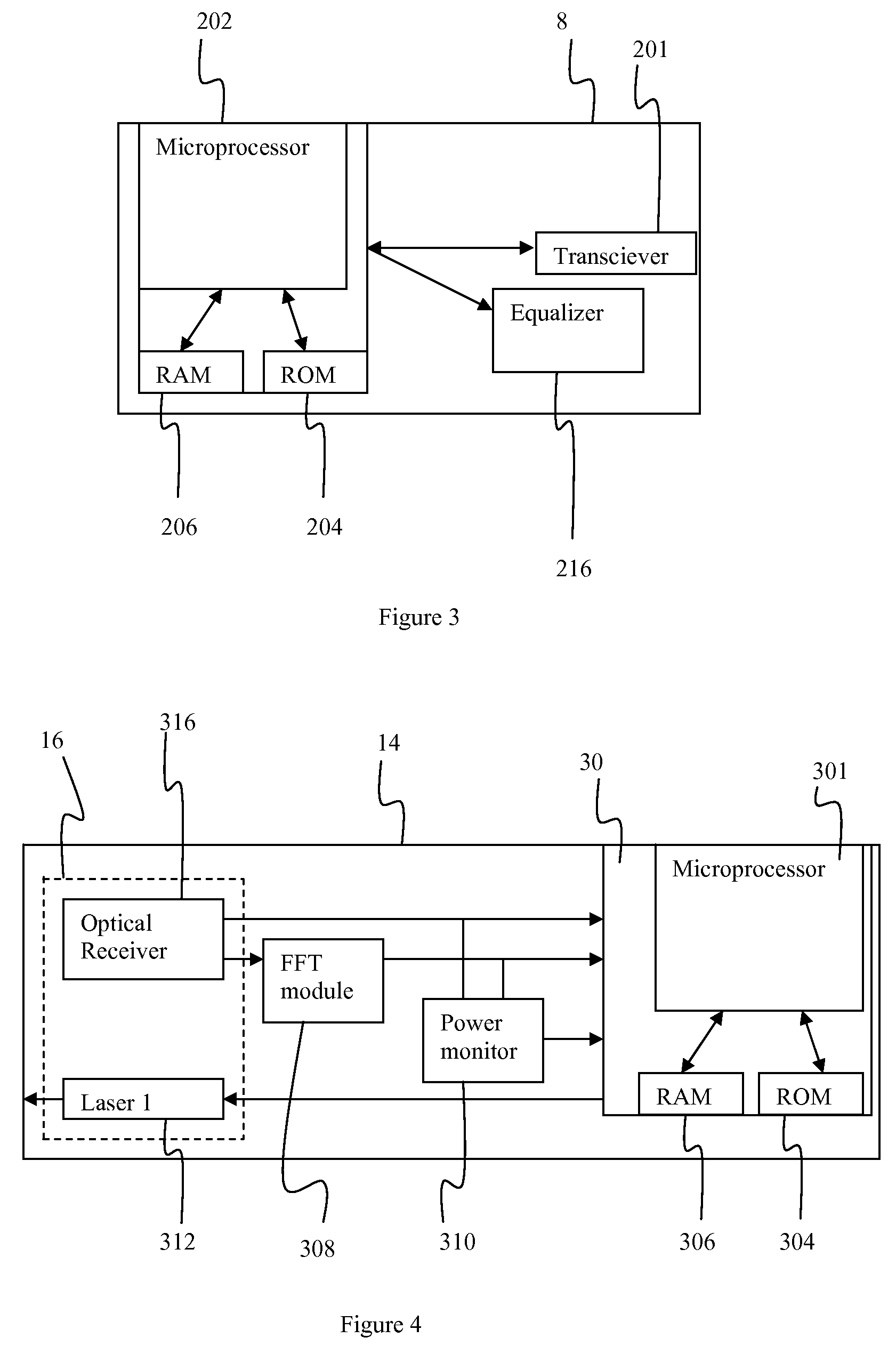
[0020]Those of skill in the art will appreciate that the automated technique of this invention allows an operator to determine which optical node each network element resides on without the need for placing test instrumentation remotely in the cable plant. In addition, the technique disclosed in the invention does not require an operator or technician to be dispatched to remote locations in the HFC network. All measurements may be made through the use of the existing terminal devices (specifically, DOCSIS terminal devices such as MTAs and cable modems) as well as headend equipment (specifically a DOCSIS CMTS). Further, the invention produces an accurate association of devices to nodes eliminating traditional error sources such as human data-entry and out of date plant maps.

Problems solved by technology

The extensive and complex networks are often difficult for a cable operator to manage and monitor.
However, when the data is inaccurate, it can often lead to misdiagnosis of issues, excessive costs associated with maintenance, and prolonged new deployments which jeopardize customer expectations.

Method used


Image

  • Efficient use of trusted third parties for additional content-sharing security
  • Efficient use of trusted third parties for additional content-sharing security
  • Efficient use of trusted third parties for additional content-sharing security

Examples


Embodiment Construction

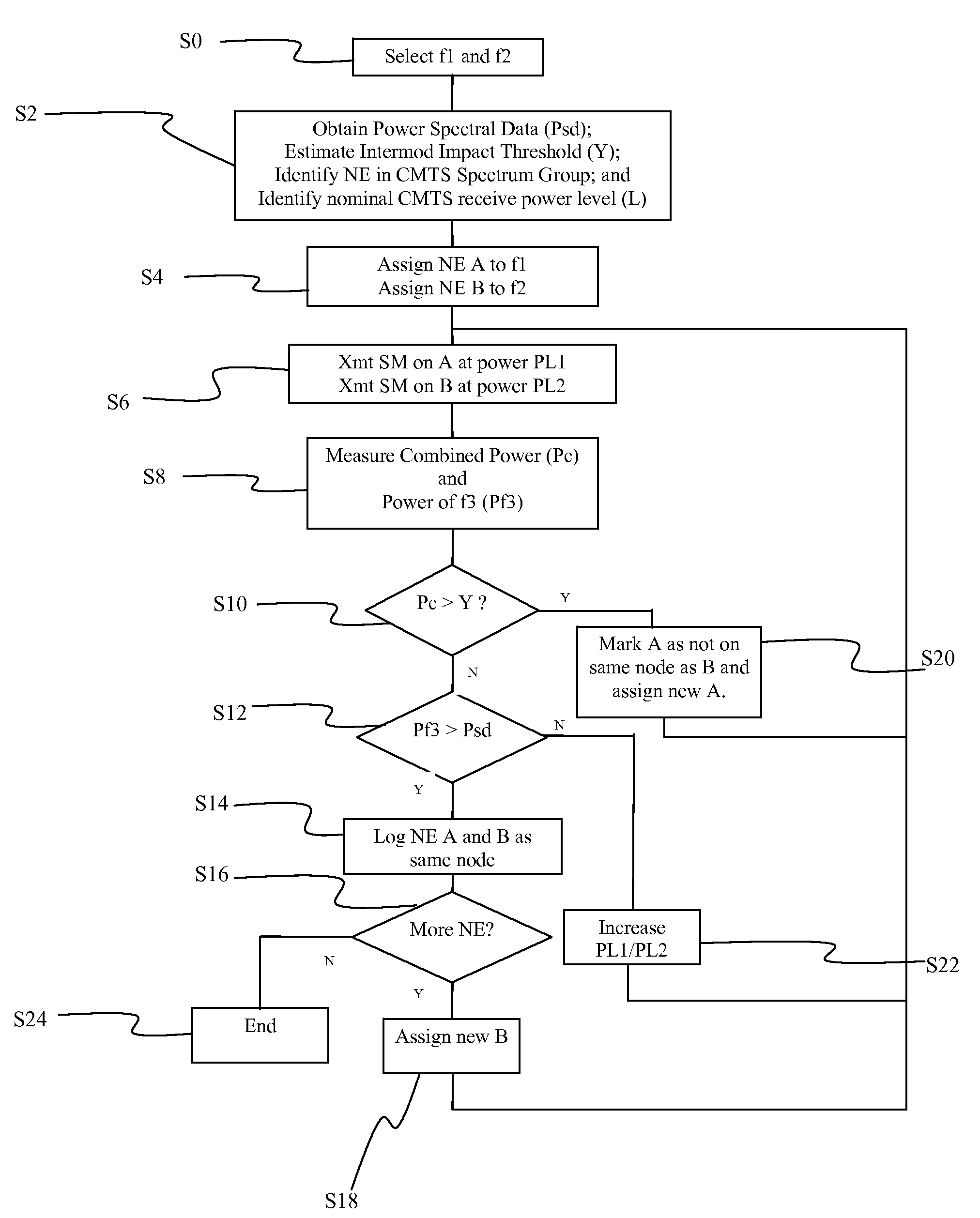
[0028]This disclosure provides a technique for automated grouping of terminal network elements together which all reside on the same optical node. The basic premise of this technique is that we can force the network elements to transmit at the same time on different frequencies; the mixing of these two simultaneous signals will generate a predictable mixing product if the two network elements are located on the same optical node and will not generate a mixing product if they are on different nodes. For optimal results, the modems must transmit at exactly same time on different channels, and the power of two signals must be adequate to trigger a detectable intermodulation distortion (“intermod”) as measured by a fast Fourier transform measurement, or other frequency selected power measurement, but not so strong as to impact active services.

[0029]Adequate margin should also be available to allow the addition of 2 DOCSIS (Data Over Cable System Interface Specification) channels. This m...


PUM


Abstract

Network elements are identified as being connected to optical nodes by instructing two network elements in a spectrum group of the CMTS to transmit at frequencies f1 and f2, respectively. Frequencies f1 and f2 are selected such that they produce intermodulation distortions (intermods) in the laser transmitter at f3 when combined. If intermods are produced which exceed a predetermined threshold, then the two network elements are determined to be on the same node. If the total power of the signal by the laser transmitter exceeds an impact threshold, then the test is stopped and new network elements are selected for testing.

Description

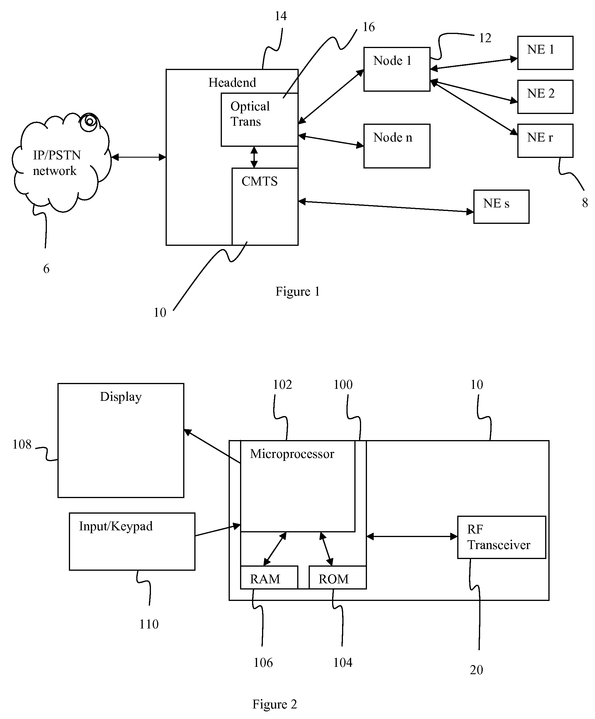
FIELD OF THE INVENTION[0001]This disclosure is directed toward mapping terminal network devices to associated optical nodes. More specifically, this disclosure is directed toward an automated approach to mapping terminal network devices to associated optical nodes.BACKGROUND OF THE INVENTION[0002]Coaxial cable television systems have been in widespread use for many years and extensive networks have been developed. The extensive and complex networks are often difficult for a cable operator to manage and monitor. A typical cable network generally contains a headend which is usually connected to several nodes which provide access to an IP or ISPN network. The headend also interfaces with a cable modem termination system (CMTS) which typically contains several receivers, each receiver typically connects to several nodes each of which connect to several network elements, such as modems, MTA (media terminal adaptors) and set top boxes of many subscribers, e.g., a single receiver may be co...

Claims


Application Information

Patent Timeline
Patent Type & Authority Patents(United States)
IPC IPC(8): H04B10/08H04B17/00
CPCH04B10/0773
Inventor COOPER, MICHAEL J.MOORE, CHARLES S.MORAN, JOHN L.THOMPSON, ROBERT J.
Owner GOOGLE TECHNOLOGY HOLDINGS LLC
Learn More