Carrying structure for a vehicle battery pack

a vehicle battery pack and carrying structure technology, applied in the direction of cell components, cell component details, electrochemical generators, etc., can solve the problems of difficult operation and inefficiency, and achieve the effect of convenient battery pack maintenance and replacement operations

Inactive Publication Date: 2010-06-29
NISSAN MOTOR CO LTD
View PDF12 Cites 24 Cited by
  • Summary
  • Abstract
  • Description
  • Claims
  • Application Information

AI Technical Summary

Benefits of technology

[0007]The present invention relates to overcoming the disadvantages of the related art by providing a carrying structure for a vehicle battery pack that allows battery pack maintenance and replacement operations to be performed more easily.
[0009]According to the carrying structure for a vehicle battery pack of the present invention, by tipping the seat toward the front of the vehicle via the tip-up mechanism, easy access to the battery pack arranged at the step portion is gained. As a result, battery pack maintenance and replacement operations can be performed efficiently.

Problems solved by technology

Consequently, when battery pack maintenance or replacement operations are to be performed, a worker cannot access the battery pack unless the rear seat and seat rails are temporarily removed, making the operation difficult and inefficient.

Method used


Image

  • Carrying structure for a vehicle battery pack
  • Carrying structure for a vehicle battery pack
  • Carrying structure for a vehicle battery pack

Examples


Embodiment Construction

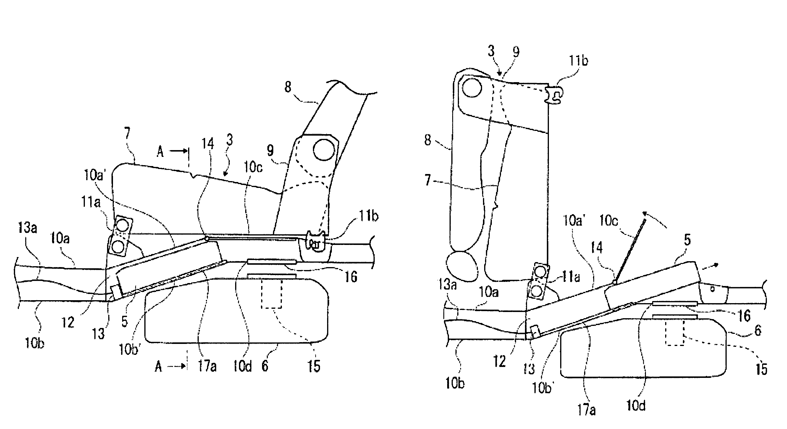
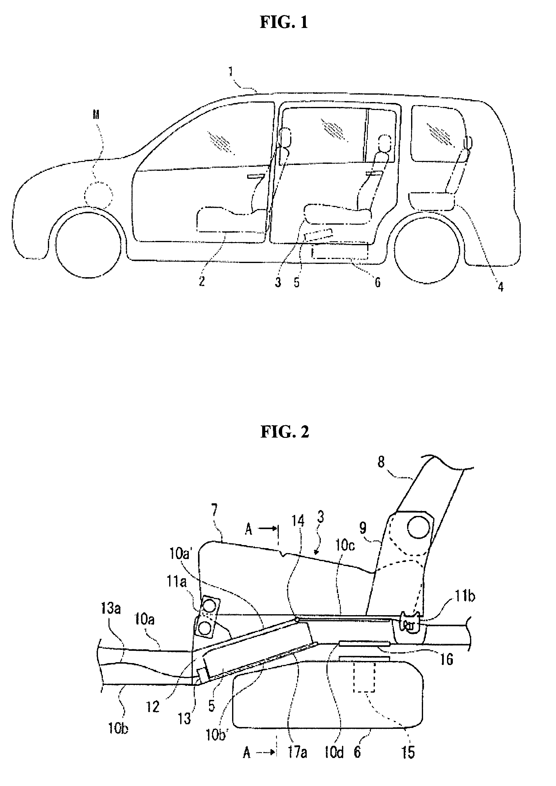
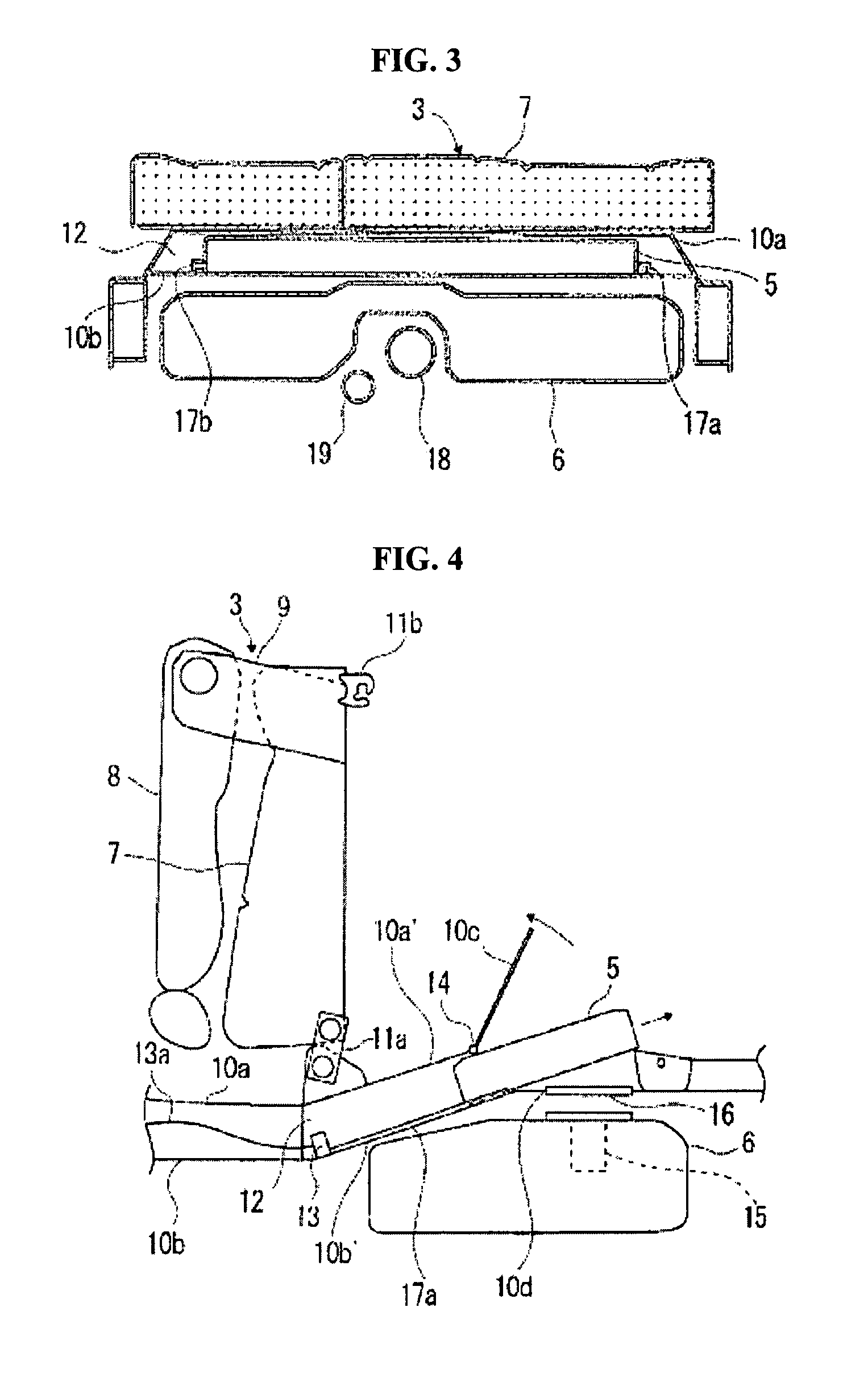
[0019]FIG. 1 is a schematic side view illustrating a carrying structure for a vehicle battery pack according to an embodiment of the present invention, in connection with a hybrid automobile having three rows of seats. FIG. 2 is a schematic diagram illustrating the portion near the rear seat (i.e. the second row of seats) of the vehicle including the carrying structure for the vehicle battery pack. FIG. 3 is a cross section taken across A-A in FIG. 2. In FIGS. 1 and 2, the front of the vehicle is to the left side, and the rear of the vehicle is to the right side.

[0020]As shown in FIG. 1, vehicle 1 is a hybrid automobile that has a front seat, second-row seat (hereinafter referred to as rear seat) 3, and third-row seat 4. Battery pack 5 for feeding electric power to driving motor M that drives the driving wheels (i.e. the rear wheels in the instant embodiment) is arranged inside the cabin below the rear seat 3, and fuel tank 6 that stores fuel, such as gasoline, to be fed to the engi...


PUM

PropertyMeasurementUnit
areaaaaaaaaaaa
electric poweraaaaaaaaaa
carrying structureaaaaaaaaaa

Abstract

A carrying structure for a vehicle battery includes a vehicle floor panel having a step portion that rises upward toward a rear of the vehicle. A battery is arranged at the step portion for feeding electric power to a driving motor that drives driving wheels of the vehicle. A seat is arranged above the battery, and a tip-up mechanism enables the seat to tip up toward a front of the vehicle with a front part of the seat serving as a rotational pivot.

Description

CROSS-REFERENCE TO RELATED APPLICATIONS[0001]This application claims priority under 35 U.S.C. §119 to Japanese Patent Application No. 2006-177868, filed on Jun. 28, 2006, the disclosure of which is incorporated by reference herein in its entirety.BACKGROUND OF THE INVENTION[0002]1. Field of the Invention[0003]The present invention relates to a type of carrying structure for a vehicle battery pack in an automobile equipped with a driving motor driven by the electric power from the battery pack.[0004]2. Description of Related Art[0005]In recent years, automobiles having a driving motor rotated by electric power from a battery (e.g. secondary battery) as a drive source have been put into practical use. Such vehicles are driven by a driving motor rotated by the electric power from the battery. Such automobiles carry a battery pack configured by connecting plural battery modules in tandem, with each battery module including plural battery cells connected in series. For conventional autom...

Claims


Application Information

Patent Timeline
Patent Type & Authority Patents(United States)
IPC IPC(8): B60R16/04H01M50/202H01M50/244H01M50/249
CPCB60K1/04H01M2/1077H01M2/1083B60K2001/0433Y02T10/7011H01M10/052H01M10/345B60L53/80Y02E60/10Y02T10/70Y02T10/7072H01M50/249H01M50/202H01M50/244
Inventor SHINDOU, TATSUYA
Owner NISSAN MOTOR CO LTD
Why Eureka
Try Eureka