
Distillation method

Active Publication Date: 2010-06-29
WHITE FOX TECH LTD
View PDF15 Cites 119 Cited by
  • Summary
  • Abstract
  • Description
  • Claims
  • Application Information

AI Technical Summary

Benefits of technology

[0010]Proceeding from this technical background, an object of the invention is to develop a distillation method that significantly improves the economy of the process, especially with respect to the dehydration of ethanol from a mash.

Problems solved by technology

In addition, regeneration of separation devices of this type is unnecessary.

Method used


Image

  • Distillation method
  • Distillation method
  • Distillation method

Examples


Embodiment Construction

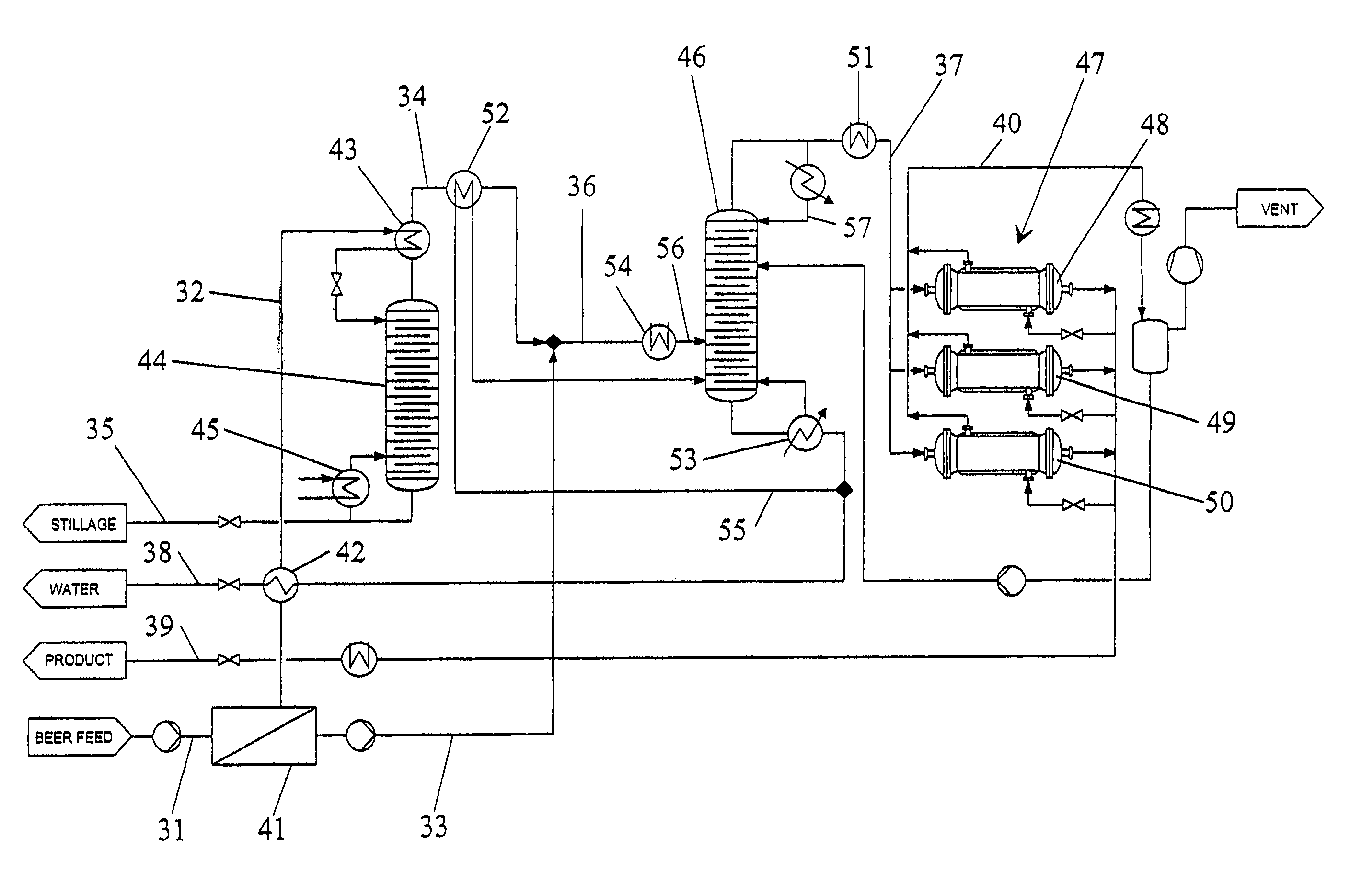
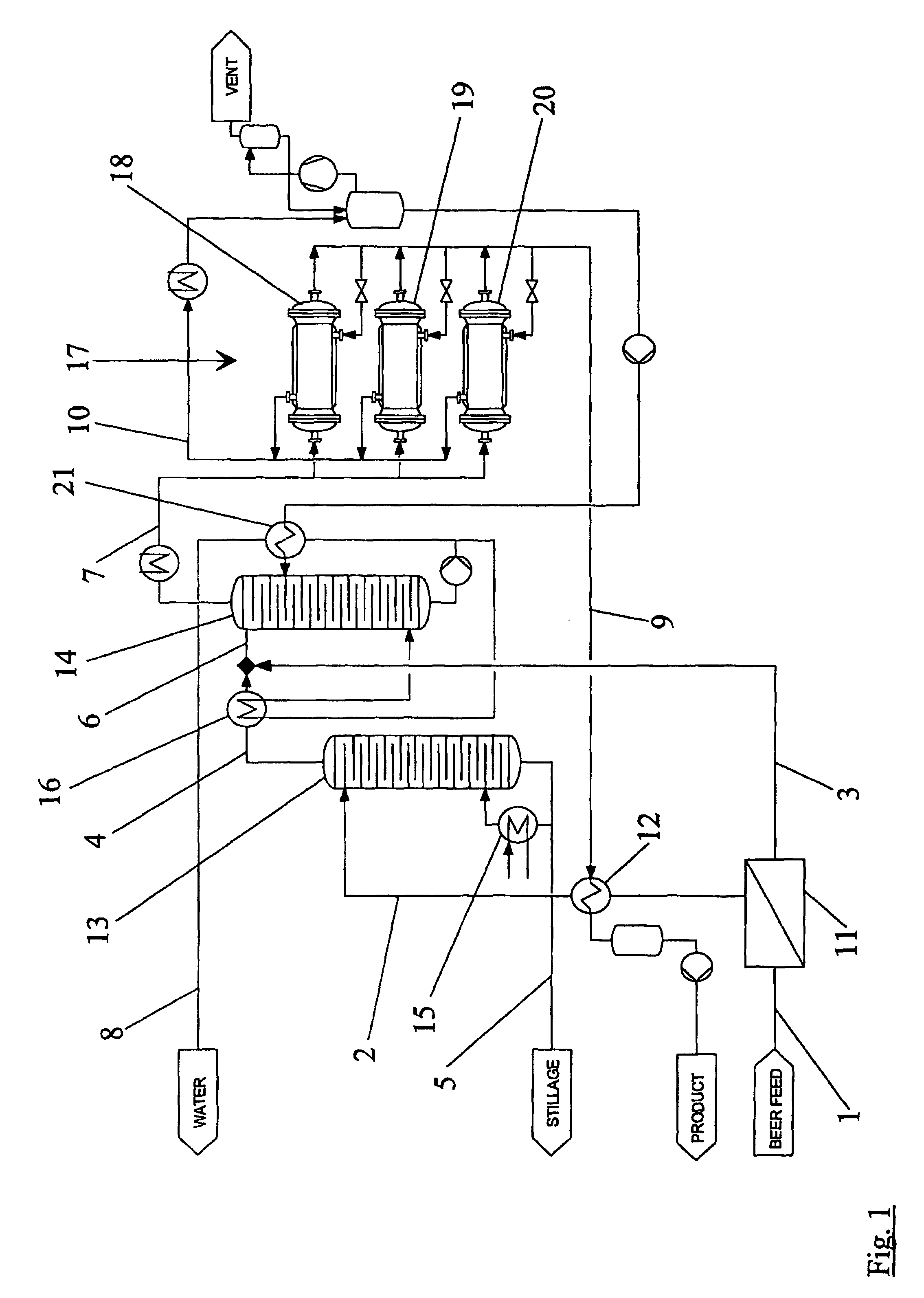
[0034]FIG. 1 is a schematic representation of a system for the distillation and dehydration of ethanol from a feed beer mash (beer feed) 1.

[0035]The mash contains about 10 wt. % ethanol, 85 wt. % water, and 5 wt. % solids at a temperature of, e.g., 20° C. In a membrane separation station 11, the feed is separated into a retentate 2 with an increased mash slurry concentration and solids and a permeate 3, which consists of a mixture of water, ethanol, and fusel oil that is present exclusively as a liquid phase. The retentate 2 with an increased mash slurry concentration and solids is heated by a heat exchanger 12, e.g., by 10° C., to a temperature of 30° C. and fed into the first distillation column 13 or stripper.

[0036]The liquid permeate 3 of the membrane separation station 11 of the feed 1 is fed directly into a second distillation column 14, which is a rectifying column.

[0037]Since the retentate 2 introduced into the first distillation column 13 has an increased mash slurry concen...


PUM

PropertyMeasurementUnit
Concentrationaaaaaaaaaa
Ratioaaaaaaaaaa
Phaseaaaaaaaaaa

Abstract

A method for distilling ethanol from a mash includes feeding a fluid to a first distillation column. The fluid and a distillate of the first distillation column are delivered to a second distillation column. The fed fluid and / or distillate of the second distillation column is / are purified in a first and / or last step of the method by a membrane separation process.

Description

CROSS-REFERENCE TO RELATED APPLICATION[0001]This is a U.S. national stage of International Application No. PCT / DE2004 / 000867, filed Apr. 24, 2004, which claims priority of German Application No. 103 19 046.5, filed Apr. 25, 2003.BACKGROUND OF THE INVENTION[0002]1. Field of the Invention[0003]The invention relates to a method of distillation, especially of ethanol from a mash.[0004]2. Description of the Related Art[0005]In a conventional method of distillation and dehydration of ethanol from a beer mash, which contains about 10% ethanol, 85% water, and 5% solids, the mash is preheated and fed into a first distillation column. In the first distillation column, the mash is concentrated by evaporation, and the solids are removed as a bottom product together with water. A portion of the bottom product is usually returned to the distillation column after heating (reboiler).[0006]The first distillate in the form of a vapor, which still contains water, ethanol, and fusel oils, is fed, possi...

Claims


Application Information

Patent Timeline
IPC IPC(8): B01D3/14B01D61/36C12G3/12B01D61/58C12H6/02
CPCB01D3/146B01D61/14B01D63/16B01D65/08B01D2311/06B01D2311/08B01D2321/2016B01D2315/02B01D2311/2669Y10S159/27Y10S203/17Y10S203/09Y10S159/28
Inventor BLUM, STEPHAN RUDIGERKAISER, BERNHARD
Owner WHITE FOX TECH LTD
Learn More