Real-time control of ion detection with extended dynamic range

a real-time control and dynamic range technology, applied in the field of detection of ions, can solve the problems of stress or ageing of specialized materials, limited dynamic range of ion detector systems, loss of sensitivity,

Active Publication Date: 2010-06-29
BRUKER DALTONIK GMBH & CO KG
View PDF7 Cites 39 Cited by
  • Summary
  • Abstract
  • Description
  • Claims
  • Application Information

AI Technical Summary

Problems solved by technology

In this case, the dynamic range of an ion detector system can be limited to the maximum input signal range of the ADC.
However, this will result in losing sensitivity because single ions can no longer be detected.
Increasing sensitivity such as by increasing gain may exceed the maximum allowable output current of the electron multiplier, and / or prematurely stress or age the specialized material that comprises the surfaces of the electron multiplier.
The means taken for extending dynamic range may reduce sensitivity, lower the precision of detected mass peaks, and, if a high sensitivity is selected, narrow the bandwidth of amplifiers employed in signal processing and / or limit the maximum scan speed of the mass analyzer.
Moreover, there has not existed a sufficient method for increasing both dynamic range and sensitivity, or at least increasing dynamic range without adversely affecting sensitivity.
For instance, because the gain is set only once per scan, the dynamic range and sensitivity of all data within that scan is effectively limited to the ion detector gain set for this scan.
To change the gain of the electron multiplier by 103, for example, one would need to change the control voltage to the multiplier by about 600 V. Therefore, the implementation of an extended dynamic range technique on a sample-by-sample basis would require a DC amplifier with close to a 600 V / μs slew rate, which in practice is very difficult to do and would require a large amount of power.
In addition, while waiting until the ion detector gain changes, one cannot collect data because the gain of the multiplier would be unknown during this time.

Method used


Image

  • Real-time control of ion detection with extended dynamic range
  • Real-time control of ion detection with extended dynamic range
  • Real-time control of ion detection with extended dynamic range

Examples


Embodiment Construction

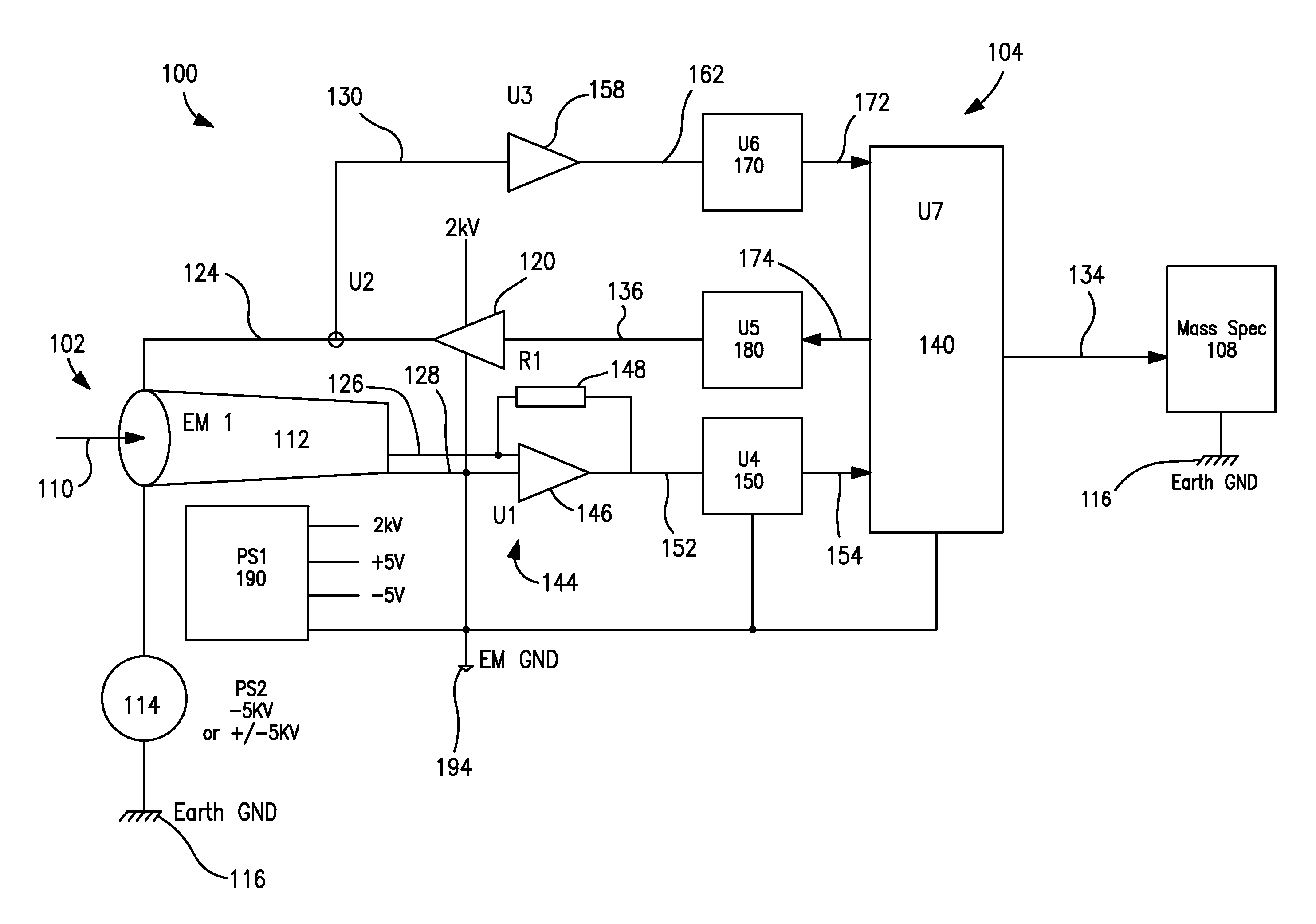
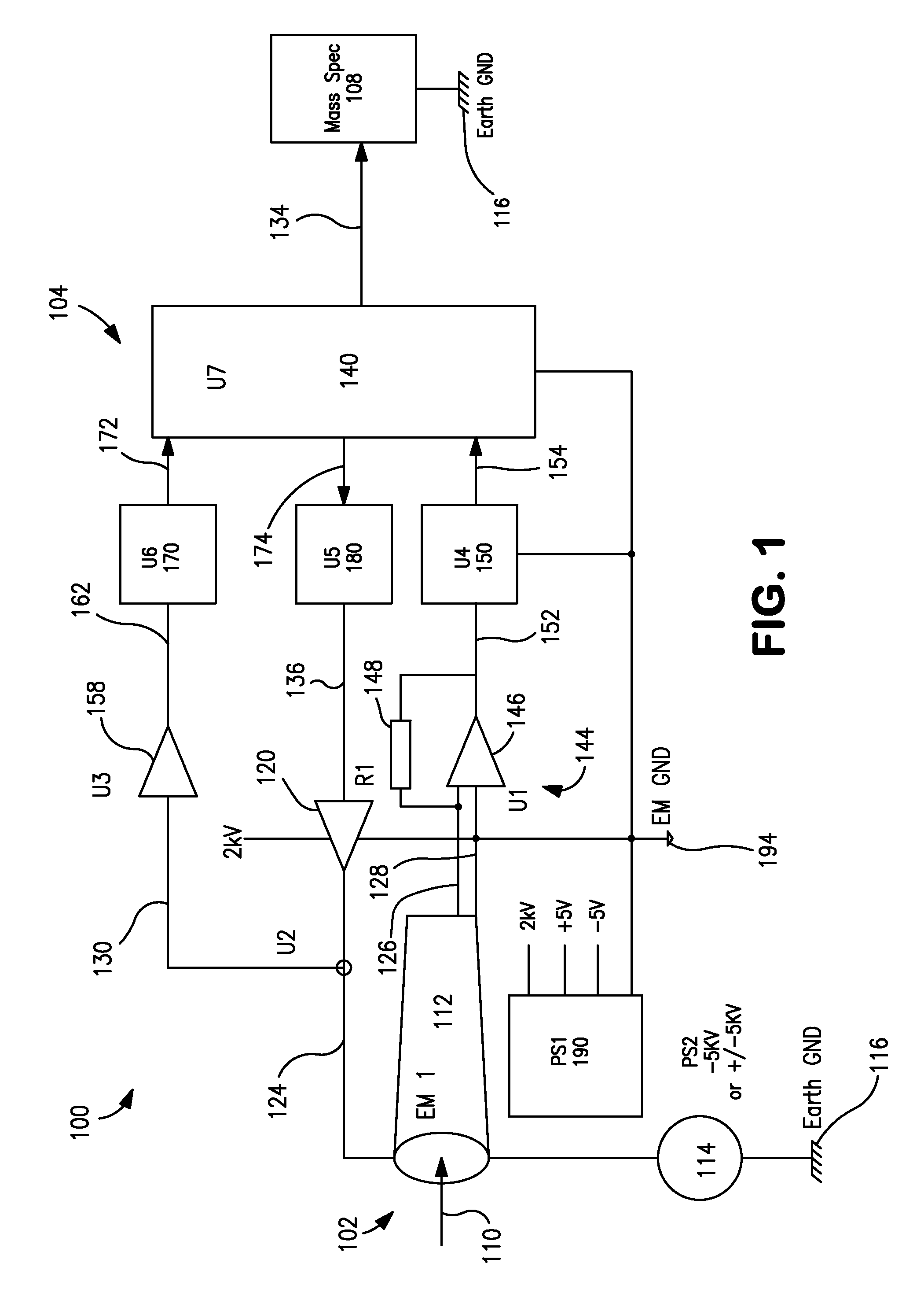
[0021]The subject matter disclosed herein generally relates to dynamic adjustment of the gain voltage (also termed control voltage or drive voltage) applied to an ion detector to improve performance. Examples of implementations of methods and related devices, apparatus, and / or systems are described in more detail below with reference to FIGS. 1-5. These examples are described in the context of mass spectrometry. However, any process that utilizes a signal multiplier or like component in conjunction with the detection of ions may fall within the scope of this disclosure. Additional examples include, but are not limited to, vacuum deposition and other fabrication processes such as may be employed to manufacture materials, electronic devices, optical devices, and articles of manufacture.

[0022]FIG. 1 illustrates certain components of a mass spectrometry (MS) system (or apparatus, device, etc.), generally designated 100. The MS system 100 includes an ion detector 102, a signal processing...


PUM


Abstract

In a method controlling an ion detector, one or more ion input signals are received at the ion detector. A data point indicative of an intensity of at least one of the received ion input signals is acquired. Asynchronously with acquiring the data point, a drive voltage applied to the ion detector is regulated to operate the ion detector at a gain optimal for the intensity of at least one of the received ion input signals. An ion detector for implementing the method is also provided.

Description

FIELD OF THE INVENTION[0001]The present invention relates generally to the detection of ions by means of ion-to-current conversion, which finds use, for example, in fields of analytical chemistry such as mass spectrometry. More particularly, the present invention relates to improving the performance of an analytical instrument such as a mass spectrometer, including its dynamic range, through control of an ion detector that receives the output of the instrument.BACKGROUND OF THE INVENTION[0002]Mass spectrometry (MS) describes a variety of instrumental methods of qualitative and quantitative analysis that enable ionizable components of a sample to be resolved according to their mass-to-charge ratios. For this purpose, a mass spectrometer converts the sample components into ions, sorts or separates the ions based on their mass-to-charge ratios, and processes the resulting ion output (ion current, flux, beam, etc.) as needed to produce a mass spectrum. Typically, a mass spectrum is a se...

Claims


Application Information

Patent Timeline
Patent Type & Authority Patents(United States)
IPC IPC(8): H01J49/26
CPCH01J49/025
Inventor STEINER, URS
Owner BRUKER DALTONIK GMBH & CO KG
Why Eureka
Try Eureka