Grid interconnection device, grid interconnection system and transfer trip system

a technology of grid interconnection and interconnection device, which is applied in emergency protective circuit arrangements, relays, transportation and packaging, etc., can solve the problems of inability to complete detection, inability to detect power supply disruption from power distribution system, and inability to perform separation processing, so as to increase the detection sensitivity of the island state

Inactive Publication Date: 2010-06-29
SANYO ELECTRIC CO LTD
View PDF6 Cites 7 Cited by
  • Summary
  • Abstract
  • Description
  • Claims
  • Application Information

AI Technical Summary

Benefits of technology

[0010]As a first aspect of the present invention, a grid interconnection device includes a power conversion circuit for converting power from a power generation device into predetermined alternating-power and connects the power generation device to a power distribution system through the power conversion circuit and a relay. The grid interconnection device includes: a relay controller configured to control separation or interconnection of the relay; a receiver configured to receive, from a predetermined transmission path, power failure information containing at least local area information indicating an area in which a power failure occurs; a determination unit configured to determine an occurrence of a power failure in the power distribution system, when the power failure information includes local area information of an area to which the power distribution system belongs; and a detector configured to detect an islanding state. The detector increases detection sensitivity of the islanding state when the determination unit determines the power failure occurs in the power distribution system. The relay controller performs separation control for the relay when the islanding state is detected by the detector.
[0011]In the grid interconnection device according to the first aspect, the detector may increase the detection sensitivity by lowering a detection threshold.
[0012]The grid interconnection device according to the first aspect further includes an output controller configured to change an output state of power outputted from an inverter circuit. The output controller may increase the detection sensitivity by increasing an active variation amount.
[0018]As a third aspect of the present invention, a transfer trip system includes a power distributing substation and a grid interconnection system, which are connected to each other through a power distribution system. The power distributing substation has a transmitter configured to transmit to the grid interconnection system, through a predetermined transmission path, power failure information containing at least local area information indicating an area in which a power failure occurs. The grid interconnection system includes a power generation device configured to generate power; a power conversion circuit configured to convert the power from the power generation device into predetermined alternating-power; a relay configured to switch between separation and interconnection of the power generation device to and from the power distribution system; a relay controller configured to control separation or interconnection of the relay; a receiver configured to receive, from the predetermined transmission path, the power failure information; a determination unit configured to determine an occurrence of a power failure in the power distribution system, when the power failure information includes local area information of an area to which the power distribution system belongs; and a detector configured to detect an islanding state. The detector increases detection sensitivity of the islanding state when the determination unit determines the power failure occurs in the power distribution system. The relay controller performs separation control for the relay when the islanding state is detected by the detector.

Problems solved by technology

However, in rare cases, disruption of power supply from the power distribution system cannot be detected and thus the separation processing is not performed.
However, complete detection cannot be achieved.

Method used


Image

  • Grid interconnection device, grid interconnection system and transfer trip system
  • Grid interconnection device, grid interconnection system and transfer trip system
  • Grid interconnection device, grid interconnection system and transfer trip system

Examples


Embodiment Construction

[0029]Next, with reference to the drawings, embodiments of the present invention will be described. Note that, in the following description of the drawings, the same or similar parts will be denoted by the same or similar reference numerals. However, it should be noted that the drawings are conceptual.

(Transfer Trip System for Power Generation Device)

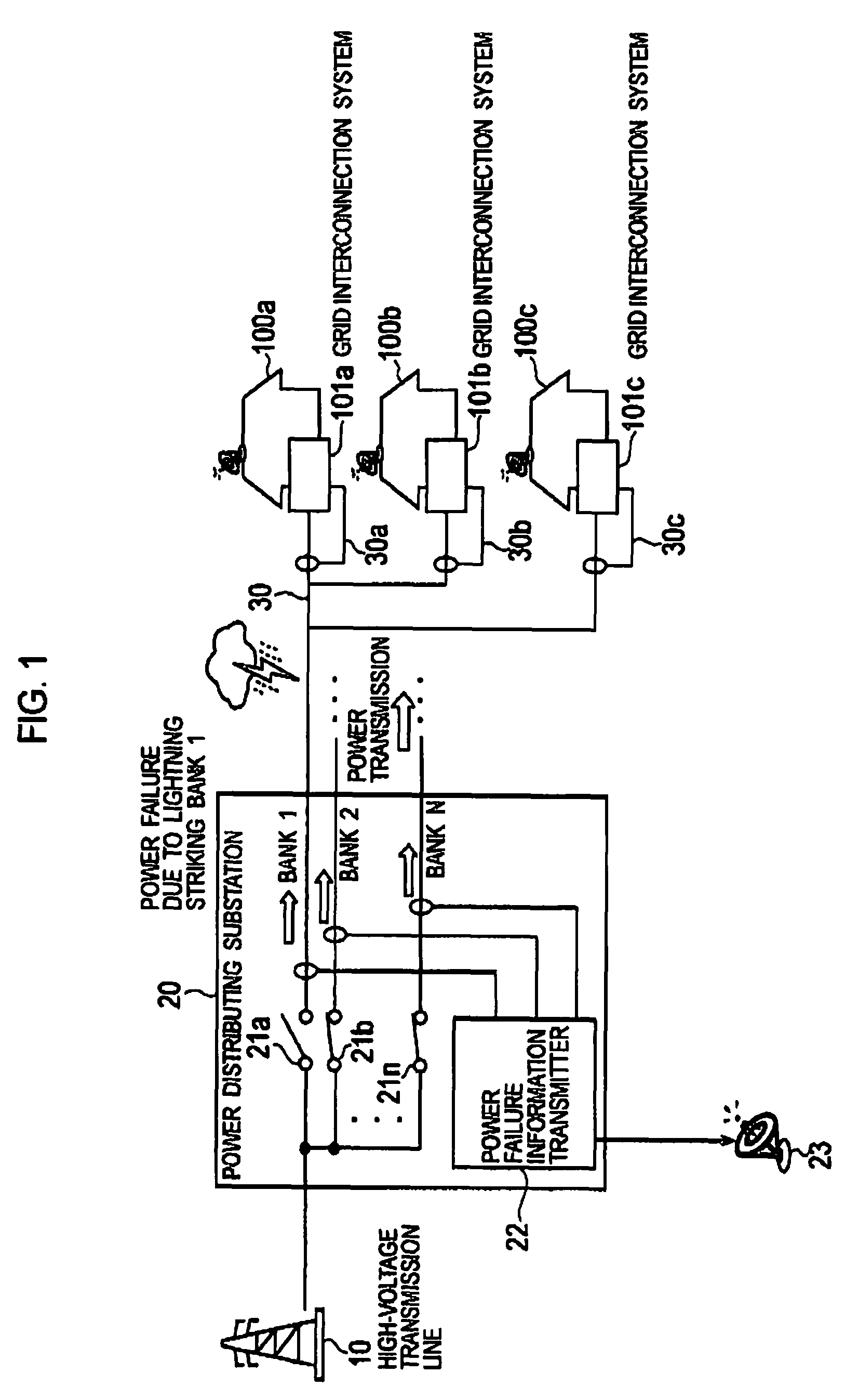
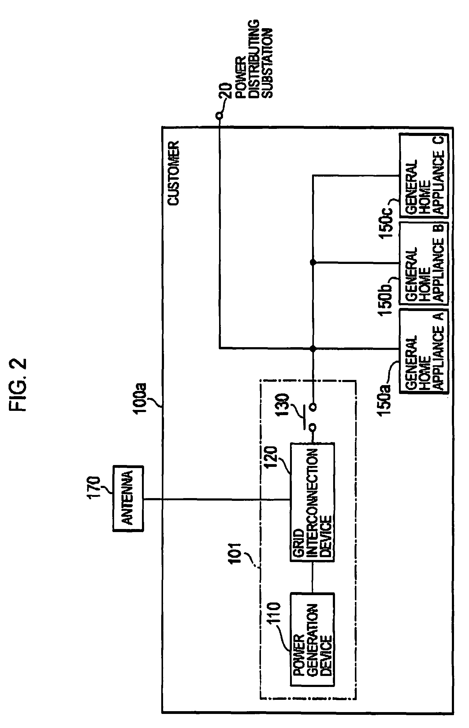
[0030]As shown in FIG. 1, a transfer trip system for power generation device according to this embodiment includes a high-voltage transmission line 10, a power distributing substation 20 and customers 100a to 100c having power generation devices. A plurality of power distribution systems (banks) are provided under the power distributing substation 20, and a large number of customers 100a to 100c are connected in parallel to the bank 1. Moreover, in the customers 100a to 100c, grid interconnection systems 101a to 101c including the power generation devices are provided, respectively. The grid interconnection systems 101a to 101c are, for...


PUM


Abstract

A grid interconnection device includes a relay controller configured to control separation or interconnection of a relay; a receiver configured to receive, from a predetermined transmission path, power failure information containing at least local area information indicating an area in which a power failure occurs; a determination unit configured to determine an occurrence of a power failure in a power distribution system, when the power failure information includes local area information of an area to which the power distribution system belongs; and a detector configured to detect an islanding state. The detector increases detection sensitivity of the islanding state when the determination unit determines the power failure in the power distribution system. The relay controller performs separation control for the relay when the islanding state is detected by the detector.

Description

CROSS REFERENCE TO RELATED APPLICATION[0001]This application is based upon and claims the benefit of priority from prior Japanese Patent Application No. 2006-297075, filed on Oct. 31, 2006; the entire contents of which are incorporated herein by reference.BACKGROUND OF THE INVENTION[0002]1. Field of the Invention[0003]The present invention relates to a grid interconnection device and a grid interconnection system which includes a power conversion circuit for converting power from a power generation device into predetermined alternating-power, and which connects the power generation device to a power distribution system through the power conversion circuit and a relay.[0004]2. Description of the Related Art[0005]Conventionally, there has been known a system, as shown in FIG. 1, in which a plurality of power distribution systems (banks) are arranged under a power distributing substation 20, and in which a large number of customers 100a to 100c are connected in parallel to a bank 1. Sp...

Claims


Application Information

Patent Timeline
Patent Type & Authority Patents(United States)
IPC IPC(8): H02J3/00H02H3/00
CPCH02J3/38H02H7/28H02J2003/388H02J3/388
Inventor ITO, KAZUOHORIO, WATARUMAKINO, MASAHIROHAGIHARA, RYUZOTATSUMI, HARUHIKOISHIDA, TAKEOTAJIMA, OSAMU
Owner SANYO ELECTRIC CO LTD
Why Eureka
Try Eureka