
AC to DC converter with power factor correction

a converter and power factor technology, applied in the direction of electric variable regulation, process and machine control, instruments, etc., can solve the problems of not being able to meet the requirements of many applications, and achieve the effects of reducing input current harmonics, high efficient input current, and reducing switching loss

Active Publication Date: 2010-06-29
FLEXTRONICS AP LLC
View PDF21 Cites 13 Cited by
  • Summary
  • Abstract
  • Description
  • Claims
  • Application Information

AI Technical Summary

Benefits of technology

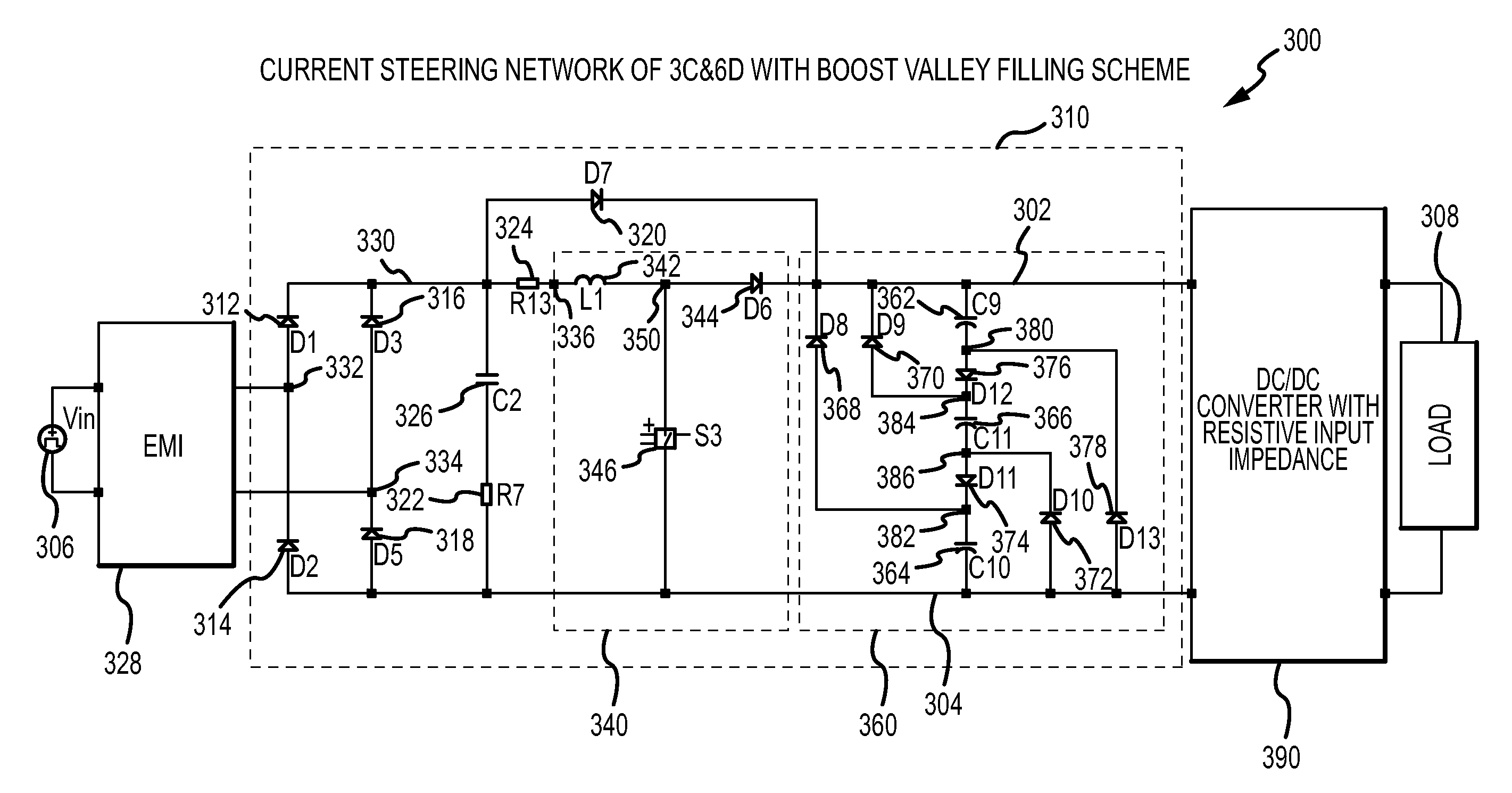
The present invention provides an AC to DC converter with a PFC front end that reduces input current harmonics and improves power factor correction. The PFC front end includes a current steering circuitry that reduces harmonic components present in the input current waveform received from the alternating current source. The current steering circuitry may include three capacitors and six diodes arranged in a network with six nodes. The PFC front end also includes a valley filling circuitry that reduces the presence of discontinuities in the input current waveform. The AC to DC converter with a PFC front end has a high power factor and low harmonics, and reduces switching loss while keeping a high power factor.

Problems solved by technology

However, conventional AC to DC power converters have high harmonic input currents and their efficiency is not as good as desired for many applications.

Method used


Image

  • AC to DC converter with power factor correction
  • AC to DC converter with power factor correction
  • AC to DC converter with power factor correction

Examples


Embodiment Construction

[0024]FIG. 3 shows a schematic diagram of one embodiment of a power converter 300. The power converter 300 includes a valley fill circuit 340, a current steering network 360, and a DC / DC converter 390. The valley fill circuit 340, the current steering network 360, and the DC / DC converter 390 are connected to one another at node 302. The valley fill circuit 340, the current steering network 360 and the DC / DC converter 390 are also connected to common node 304. Common node 304 may be referred to herein as the ground reference or simply ground. The power converter 300 is connectable to an alternating current source 306 (e.g., an electrical outlet) and operates to convert an input alternating current to direct current that may be supplied to a load 308. Together, the valley filling circuit 340 and the current steering circuit 360 comprise a PFC front end 310. In other embodiments, such as described herein in connection with FIGS. 5 and 9, valley filling circuitry is not included in the ...


PUM


Abstract

An input current shaping AC to DC converter with PFC front end that reduces input current harmonics is provided. In one embodiment, an AC to DC converter connectable with an alternating current source and operable to output a direct current has a PFC front end followed by a DC / DC converter. The PFC front end reduces harmonic components present in an input current waveform received by the PFC front end from the alternating current source and includes current steering circuitry and, optionally, valley filling circuitry. The DC / DC converter is one that presents pure resistive input impedance to the PFC front end. The DC / DC converter outputs the direct current to a load connected thereto.

Description

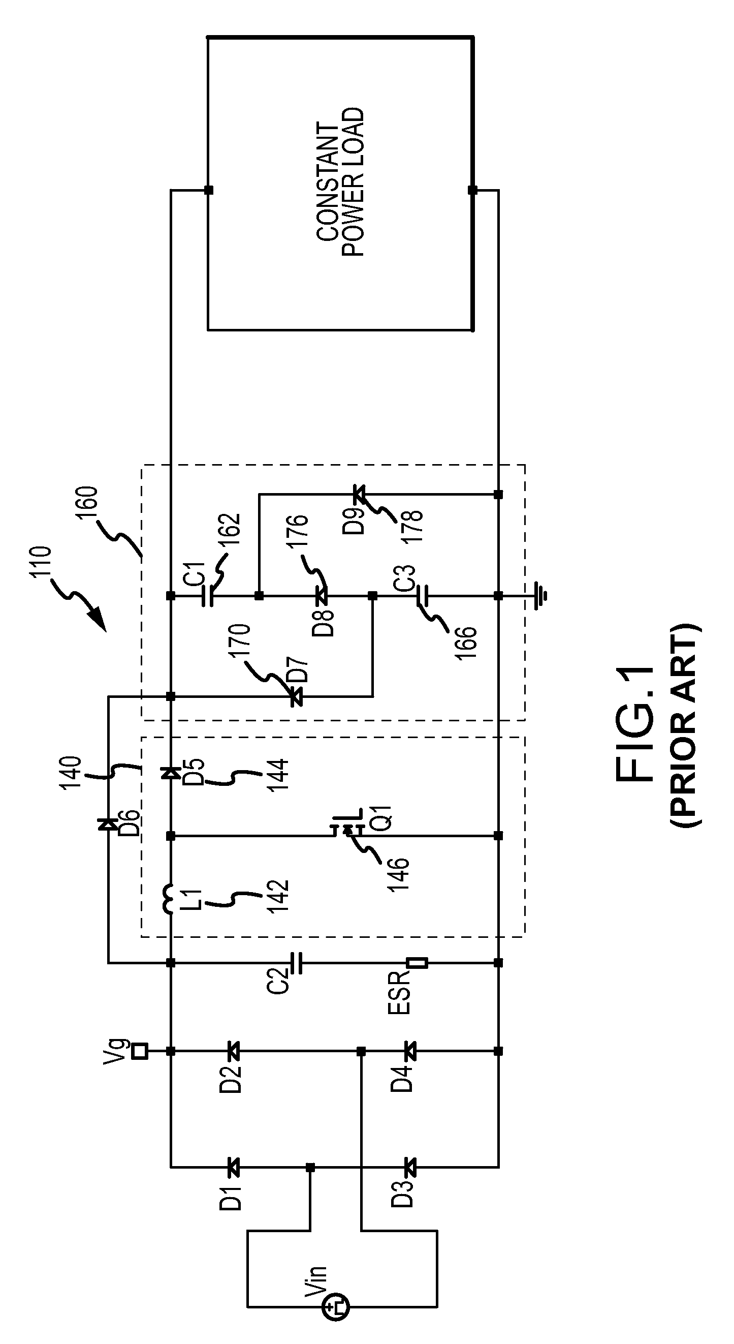
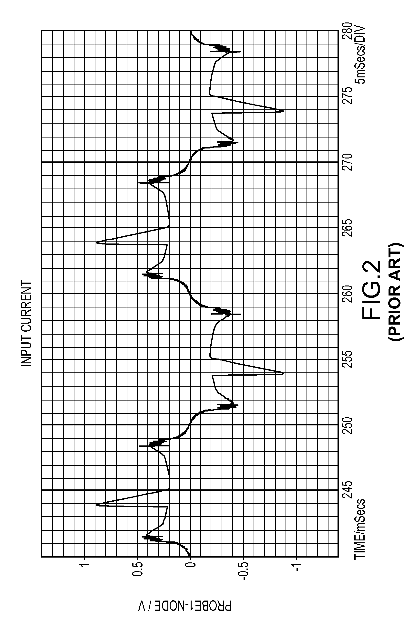
FIELD OF THE INVENTION[0001]The present invention relates generally to power converters, and more particularly to alternating current (AC) to direct current (DC) converters with power factor corrective (PFC) requirements.BACKGROUND OF THE INVENTION[0002]AC to DC power converters with PFC capability are desirable in a number of applications including, for example, in laptop and desktop computers. However, conventional AC to DC power converters have high harmonic input currents and their efficiency is not as good as desired for many applications. In this regard, FIG. 1 is a schematic diagram of one prior art AC to DC converter with PFC front end 110. As shown, the PFC front end 110 includes a valley filling circuit 140 (inductor 142, diode 144 and transistor 146) and a current steering network 160 having two capacitors 162, 166 and three diodes 170, 176, 178 arranged in a network with four nodes. FIG. 2 is a plot of a simulated input current waveform 202 for the PFC front end 110 show...

Claims


Application Information

Patent Timeline
Patent Type & Authority Patents(United States)
IPC IPC(8): G05F1/70
CPCH02M1/4225Y02B70/126Y02B70/10
Inventor GARRITY, PAULYANG, ZAOHONG
Owner FLEXTRONICS AP LLC
Learn More