
Reference voltage generating circuit and liquid display device using the same

a reference voltage and generating circuit technology, applied in the direction of power conversion systems, instruments, optics, etc., can solve the problems of shortening the level transition period of the common voltage, affecting so as to prevent the quality of display images from deteriorating from noise components

Inactive Publication Date: 2010-06-29
LG DISPLAY CO LTD
View PDF2 Cites 7 Cited by
  • Summary
  • Abstract
  • Description
  • Claims
  • Application Information

AI Technical Summary

Benefits of technology

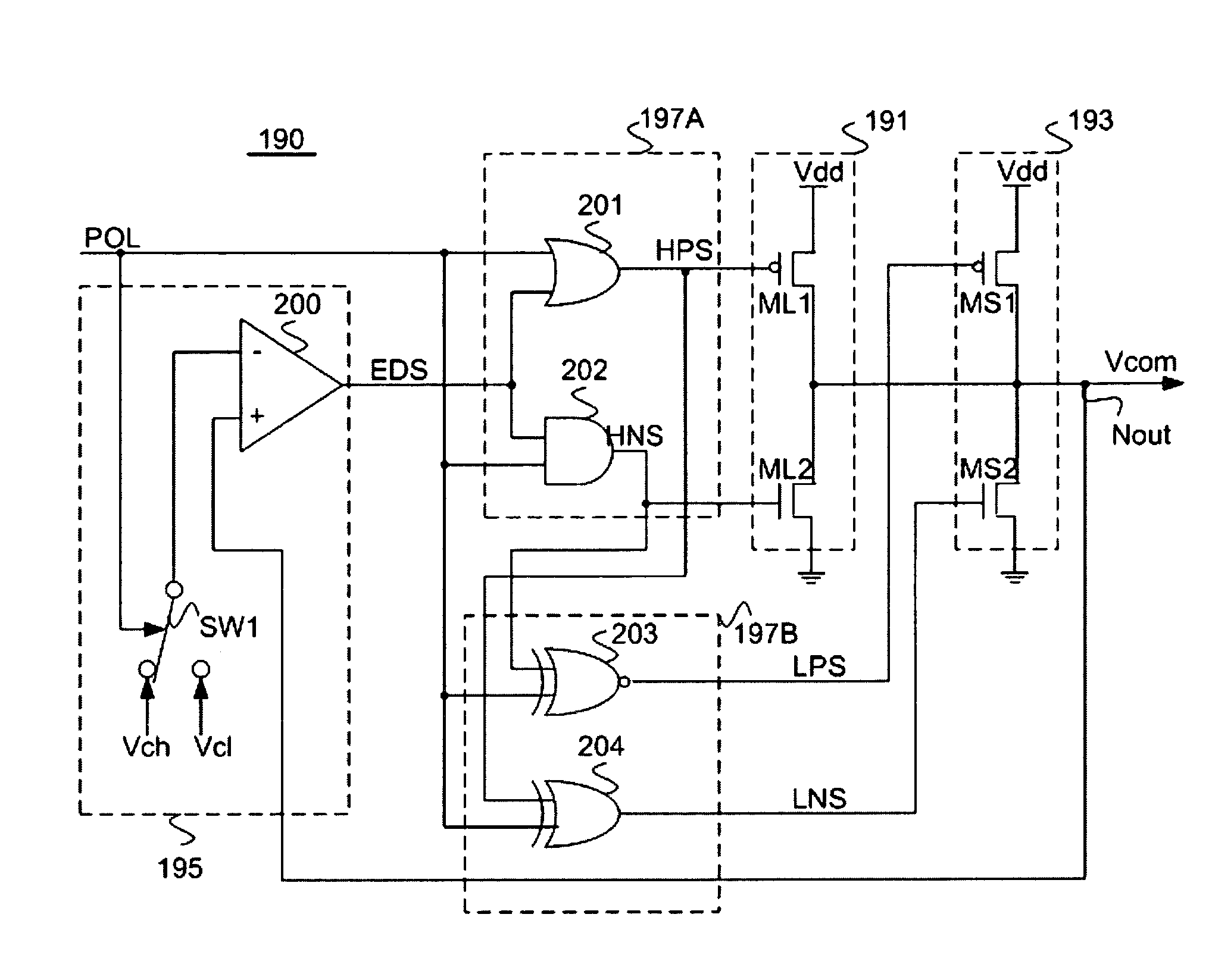
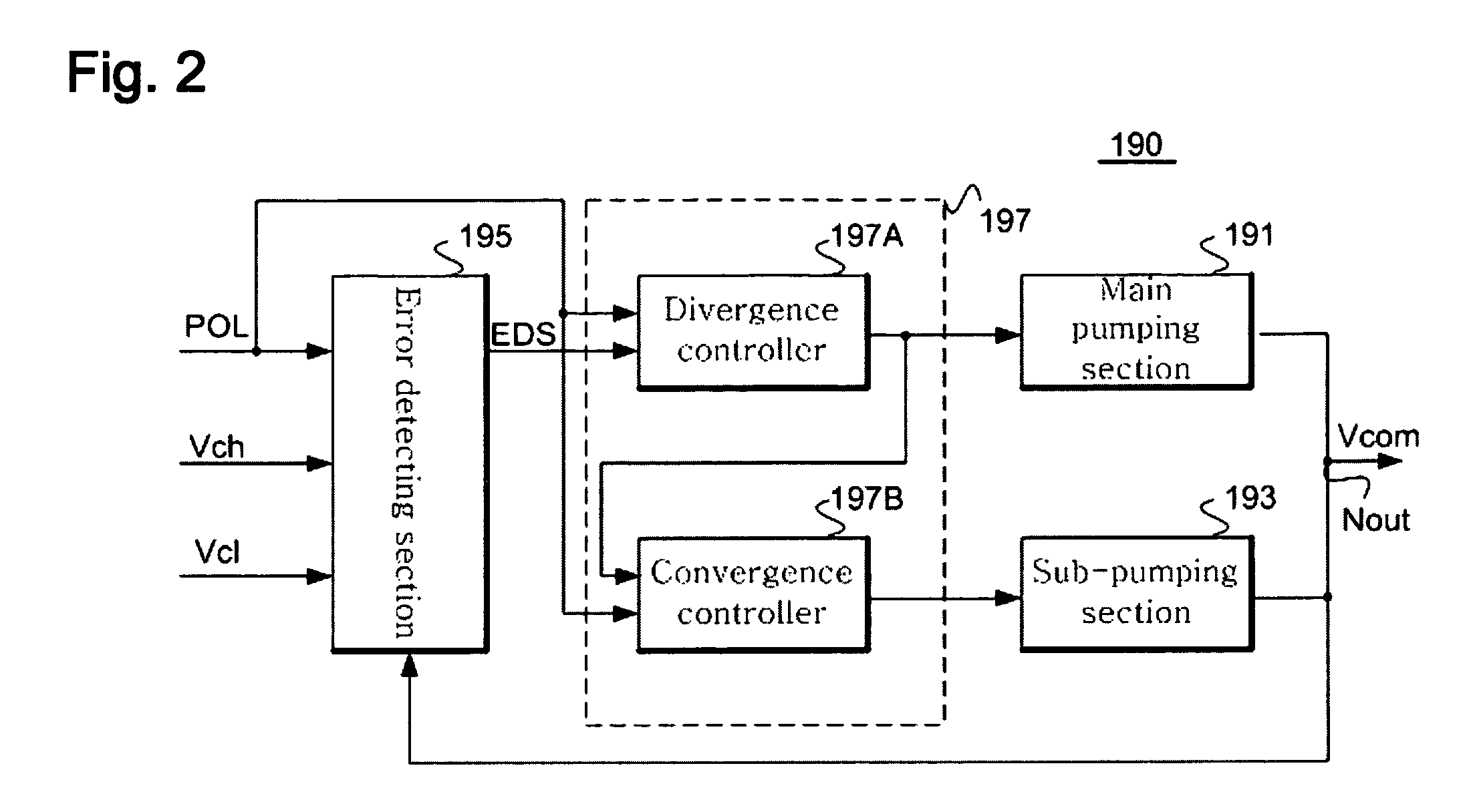
The present invention provides a reference voltage generating circuit for an LCD device that overcomes limitations and disadvantages of related art. The circuit includes a main pumping section, a sub-pumping section, an input section, and a control section. The control section alternately compares an output voltage with first and second reference levels to selectively output a logic level. The main pumping section selectively lowers the output voltage in a fast negative pumping and the sub-pumping section selectively raises the output voltage in a slower positive pumping. The circuit also includes a common voltage generator that alternately has a first reference level and a second reference level to supply a common voltage with rapid divergence and slow convergence characteristics to the common electrode. The reference voltage generating circuit can selectively output a logic level using at least two bits of level selecting signals and has rapid divergence and slow convergence characteristics. The technical effects of the invention include stable reference voltage, prevention of noise component deteriorating the quality of a displayed image, and improved display quality.

Problems solved by technology

The high capacity transistor provided in the related art common voltage generating circuit can shorten the level transition period of the common voltage but cannot maintain a stable transition level.
The oscillation phenomenon adds a noise component to a pixel data voltage and deteriorates the quality of the displayed image on the LCD device.

Method used


Image

  • Reference voltage generating circuit and liquid display device using the same
  • Reference voltage generating circuit and liquid display device using the same
  • Reference voltage generating circuit and liquid display device using the same

Examples


Embodiment Construction

[0021]Reference will now be made in detail to exemplary embodiments of the present invention, which are illustrated in the accompanying drawings. Wherever possible, the same reference numbers will be used throughout the drawings to refer to the same or like parts.

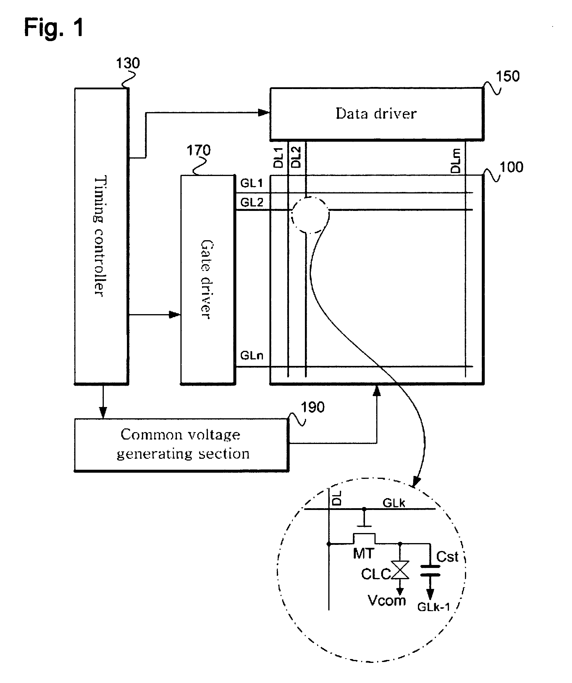
[0022]FIG. 1 is a schematic diagram of an exemplary LCD device according to an embodiment of the present invention. Referring to FIG. 1, a liquid crystal display device includes a liquid crystal panel 100 displaying an image, a data driver 150 for driving m-number of data lines DL1 to DLm on the liquid crystal panel 100, a gate driver 170 for driving n-number of gate lines GL1 to GLn on the liquid crystal panel 100, and a timing controller 130 controlling the drive timings of the data and gate drivers 150 and 170.

[0023]The liquid crystal panel 100 includes pixels formed by regions defined by n-number of gate lines GL1 to GLn and m-number of data lines DL1 to DLm crossing each other, respectively. Each of the pixels includes...


PUM


Abstract

A reference voltage generating circuit for an LCD device includes a main pumping section, a sub-pumping section, an input section inputting a level designating signal periodically and alternately designating a first reference level and a second reference level, and a control section alternately comparing an output voltage with the first and second reference levels in response to the level designating signal, wherein the control section outputs a first logic level and the main pumping section selectively lowers the output voltage in a fast negative pumping and the sub-pumping section selectively raises the output voltage in a slower positive pumping.

Description

[0001]This application claims the benefit of Korean Patent Application No. 10-2006-0060200, filed on Jun. 30, 2006, which is hereby incorporated by reference in its entirety.BACKGROUND OF THE INVENTION[0002]1. Field of the Invention[0003]Embodiments of the present invention relate to a liquid crystal display (LCD) device, and more particularly, to a reference voltage generating circuit for an LCD device. Embodiments of the present invention are suitable for a wide scope of applications. In particular, embodiments of the present invention are suitable for generating and maintaining voltages at a plurality of levels for the LCD device.[0004]2. Discussion of Related Art[0005]In general, a signal processing and control system uses a reference voltage signal to detect a desired signal. The signal processing and control system periodically changes signal modes and control states as needed. Accordingly, the reference voltage signal may alternate between at least two voltage levels dependin...

Claims


Application Information

Patent Timeline
Patent Type & Authority Patents(United States)
IPC IPC(8): G09G3/36
CPCG09G3/3655G09G3/3614G09G2320/0247G09G3/36G02F1/133G09G3/20H02M1/14
Inventor LEE, BU YEOL
Owner LG DISPLAY CO LTD
Learn More