Flying mobile on-board ellipsometer, polarimeter, reflectometer and the like systems

Inactive Publication Date: 2010-06-29
J A WOOLLAM CO
View PDF30 Cites 15 Cited by
  • Summary
  • Abstract
  • Description
  • Claims
  • Application Information

AI Technical Summary

Benefits of technology

[0139]An improvement provided by the present invention is a means for providing gas sequestered in a formed “mini-chamber” in the vicinity of a location on a surface of a sample during investigation thereof by electromagnetic radiation. While similar in purpose to the system described in U.S. Pat. No. 6,813,026 to McAninch, (the system of which can be applied in the present invention), taking guide from the J.A. Woollam VUV system described briefly in the Background Section, which provides a reduced gas flow mode, the present invention does not necessarily require a continuous flow of gas during use. Rather, the present invention system can provide means for forming a “mini-chamber” which accesses therewithin at least a portion of a sample.

Problems solved by technology

They can read PSI and DELTA of a Material System over a full Range of Degrees with the only limitation being that if PSI becomes essentially zero (0.0), one can't then determine DELTA as there is not sufficient PSI Polar Vector Length to form the angle between the PSI Vector and an “X” axis.
However, while it is relatively easy to provide Wavelength change without extensive difficult physical Ellipsometer System Orientation change, it is typically difficult to change the Angle-of-Incidence (AOI) that a Beam of Electromagnetic Radiation makes to a surface of a sample system.
An (

Method used


Image

  • Flying mobile on-board ellipsometer, polarimeter, reflectometer and the like systems
  • Flying mobile on-board ellipsometer, polarimeter, reflectometer and the like systems
  • Flying mobile on-board ellipsometer, polarimeter, reflectometer and the like systems

Examples


Example

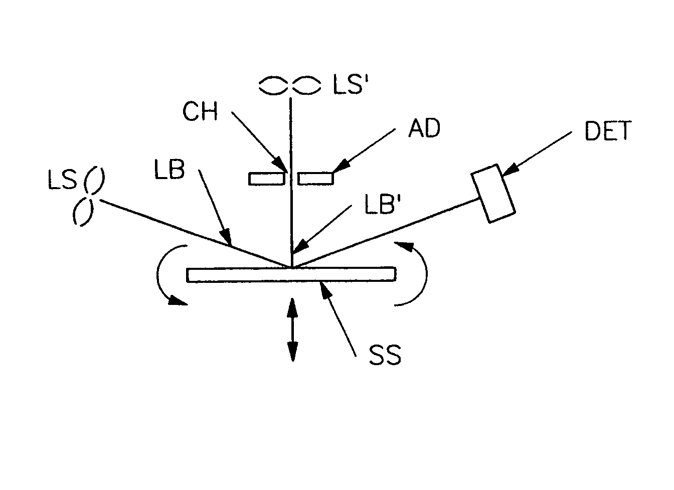
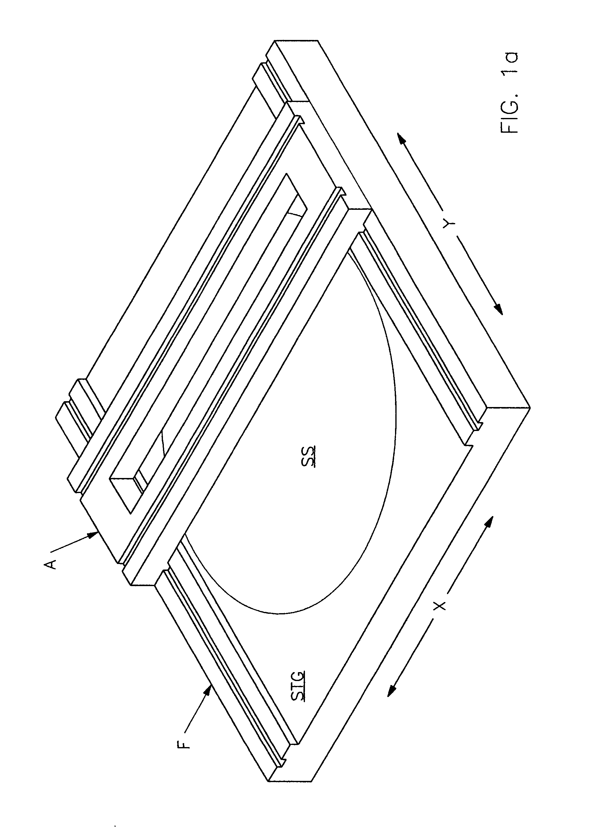
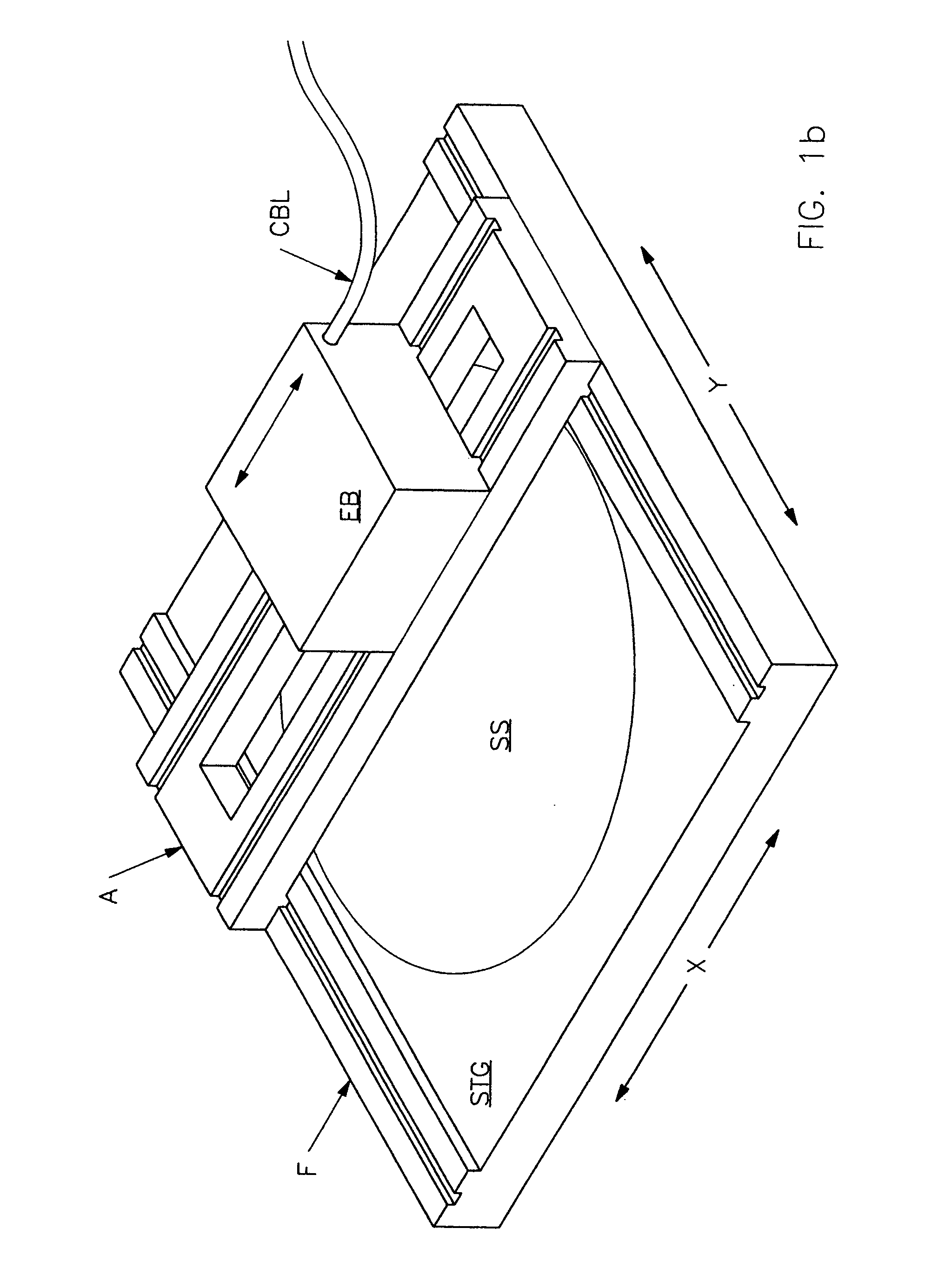
[0192]As disclosed in Parent application Ser. No. 11 / 105,852, FIGS. 1a and 1b demonstrate, in FIG. 1a, a perspective view of a Stage (STG) for supporting a large Sample (S), (eg. on the order of Feet / Meters in diameter), said Stage (STG) being being functionally combined with a Frame (F) which allows a Frame (A) to move atop thereof in a (Y) direction. Note that Frame (A) has an open middle region through which a Beam (E) of electromagnetic radiation, (for example see FIG. 2), can pass to reach the Sample (SS). FIG. 1b demonstrates addition of Black Box (EB) atop Frame (A), said Black Box (EB) being movable in an (X) direction atop Frame (A). (Note, while FIGS. 1a and 1b show that Sample facing upward, this does not limit application to a configuration wherein the shown system is rotated so that the sample faces laterally or is oriented in any other plane). While Also shown is an optional Cable (CBL) which can serve to provide electrical power into, and carry Data Detector Signals t...


PUM


Abstract

A substantially self-contained “on-board” material system investigation system for effecting relative translational and rotational motion between a source and detector of electromagnetic radiation and a sample, which system is functionally mounted on a three dimensional locational system to enable positioning at desired locations on, and distances from, the surface of a sample, including the capability to easily and conveniently effect rotation and/or to change the angle-of-incidence of a beam of electromagnetic radiation onto a sample surface and/or to provide gas flow confined in a mini-chamber near the surface of a sample, at a location at which a beam having UV, VUV, IR and/or NIR wavelengths of electromagnetic radiation is caused to be impinged thereupon.

Description

[0001]This Application directly Claims Benefit of Provisional Application Ser. No. 60 / 836,232 filed Aug. 9, 2006. This Application is directly a CIP of patent application Ser. No. 11 / 105,852 filed Apr. 14, 2005 now U.S. Pat. No. 7,277,171, and therevia this Application Claims benefit of Provisional Applications 60 / 564,747 Filed Apr. 23, 2004, and 60 / 580,314 Filed Jun. 17, 2004. This Application is further a Continuation-In-Part of Utility application Ser. Nos. 10 / 829,620 Filed Apr. 22, 2004 now U.S. Pat. No. 7,193,710; and of 10 / 925,333 Filed Aug. 24, 2004 now U.S. Pat. No. 7,265,838, and therevia of 10 / 050,802 Filed Jan. 15, 2002, (now U.S. Pat. No. 6,859,278). This Application is further a Continuation-In-Part of Utility application Ser. No. 10 / 925,333 Filed Aug. 24, 2004 now U.S. Pat. No. 7,265,838, and of 10 / 829,620 Filed Apr. 22, 2004, and is a Divisional of 10 / 050,802 Filed Jan. 15, 2002 now U.S. Pat. No. 6,859,278; and via the above Applications Claims Benefit of Provisional ...

Claims


Application Information

Patent Timeline
IPC IPC(8): G01J4/00
CPCG01N21/21G01N21/55G01N2021/151G01N2201/0693G01N2021/214G01N2201/021G01N2021/212
Inventor JOHS, BLAINE D.HE, PINGLIPHARDT, MARTIN M.GOEDEN, CHRISTOPHER A.WOOLLAM, JOHN A.WELCH, JAMES D.
Owner J A WOOLLAM CO
Why Eureka
Try Eureka