Display sign adapted to be backlit by widely spaced light emitting diodes

a diode light and backlit technology, applied in the direction of instruments, lighting and heating equipment, planar/plate-like light guides, etc., can solve the problems of high operating and maintenance costs, and high maintenance costs. the effect of 30% or more annually

Inactive Publication Date: 2010-07-06
ELLUMINEERING
View PDF22 Cites 32 Cited by
  • Summary
  • Abstract
  • Description
  • Claims
  • Application Information

AI Technical Summary

Benefits of technology

[0024]The present invention provides a backlit illuminated display sign that includes front and rear elements preferably comprising a rear sign enclosure element at the back of the sign that has a light reflective inner surface and a wide mouth opening that faces forwardly. Extending across the mouth opening is a front sign cover element. The cover includes an optically transmissive element, typically a rigid sheet of plastic resin with a provision for enabling it to function as a light propagation channel in which light rays are funneled to an image-producing opening where the light is emitted for producing an image. A light cavity is provided between the front cover and the rear sign enclosure element. At least one LED light source is operatively associated with the sign to provide visible illumination within the light cavity. The light-transmissive element is converted into a light channel by a light-reflective layer provided on its inner and outer surfaces to create a light guide. The surface layers reflect light rays within the guide that emanate from the light source back into the light guide such that the light guide acts as a light propagation channel which traps and carries the light laterally and vertically through the light guide until emitted through the opening in the outer light-reflective layer to produce visible symbols, letters, numbers, or other indicia that can be seen by an observer viewing the front surface of the sign. The inner surface of the rear sign enclosure is a highly reflective material that efficiently reflects light rays from the light source forwardly into the optically-transmissive sheet element where they are guided effectively to one or more openings on the front of the sign.

Problems solved by technology

Neon display signs while very bright are expensive to produce and subject to high operating and maintenance costs.
The maintenance costs may be as high as 30% or more annually and include glass tube breakage, transformer failure, corrosion, electrical shorts that cause fires, hazardous disposal requirements and other costs.
Other kinds of lamps such as high intensity discharge, HID, metal halide lamps are rarely used because replacement lamp cost, short lamp life, high heat inside sign box cavities and hazardous disposal of failed lamps.
This construction makes the sign expensive and complicated to construct.
In some prior LED signs, the LED's or other lights are spread somewhat farther apart but at a substantial reduction in brightness which makes the sign less useful especially for daytime operation and gives the sign less marketing appeal because it appears dim compared, for example, with a neon sign of comparable size.
Moreover, the brightness of some signs varies from one part of the sign to another, a condition sometimes referred to as “hot spots”, which is, of course, unacceptable.
Other attempts to produce signs with LED's spaced more than an inch or so apart have only resulted in signs that exhibit “hot spots”, and have a depth of over 5 inches which makes them unsuitable for many applications.
However there is no provision for channeling, confining, or guiding light rays within a sign element or for producing visible symbols on the front surface of the lens.
Moreover, black undercoating layers that are used absorb incident light present within the milky-white cover thereby reducing the brightness of the sign.

Method used


Image

  • Display sign adapted to be backlit by widely spaced light emitting diodes
  • Display sign adapted to be backlit by widely spaced light emitting diodes
  • Display sign adapted to be backlit by widely spaced light emitting diodes

Examples


Embodiment Construction

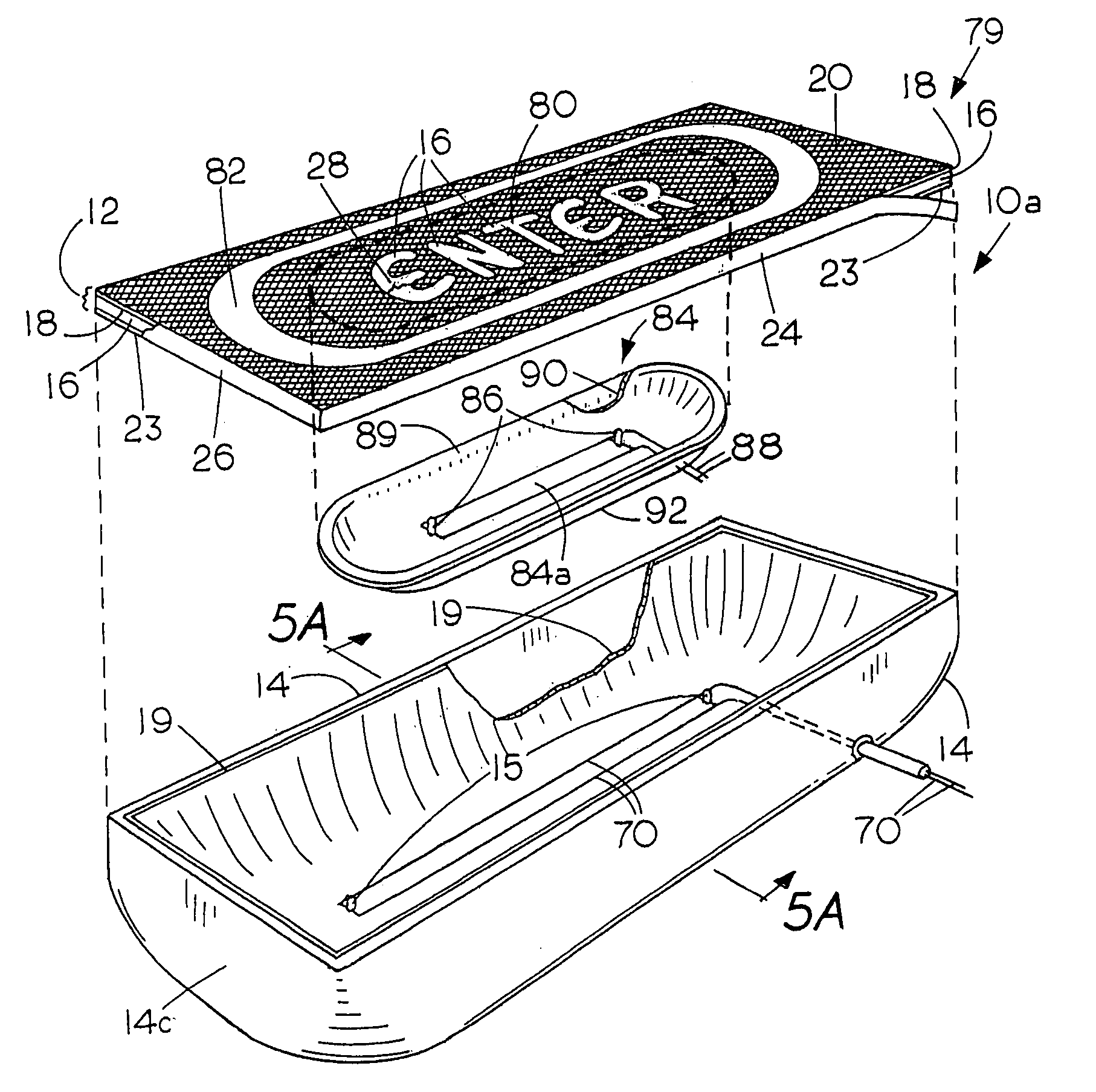
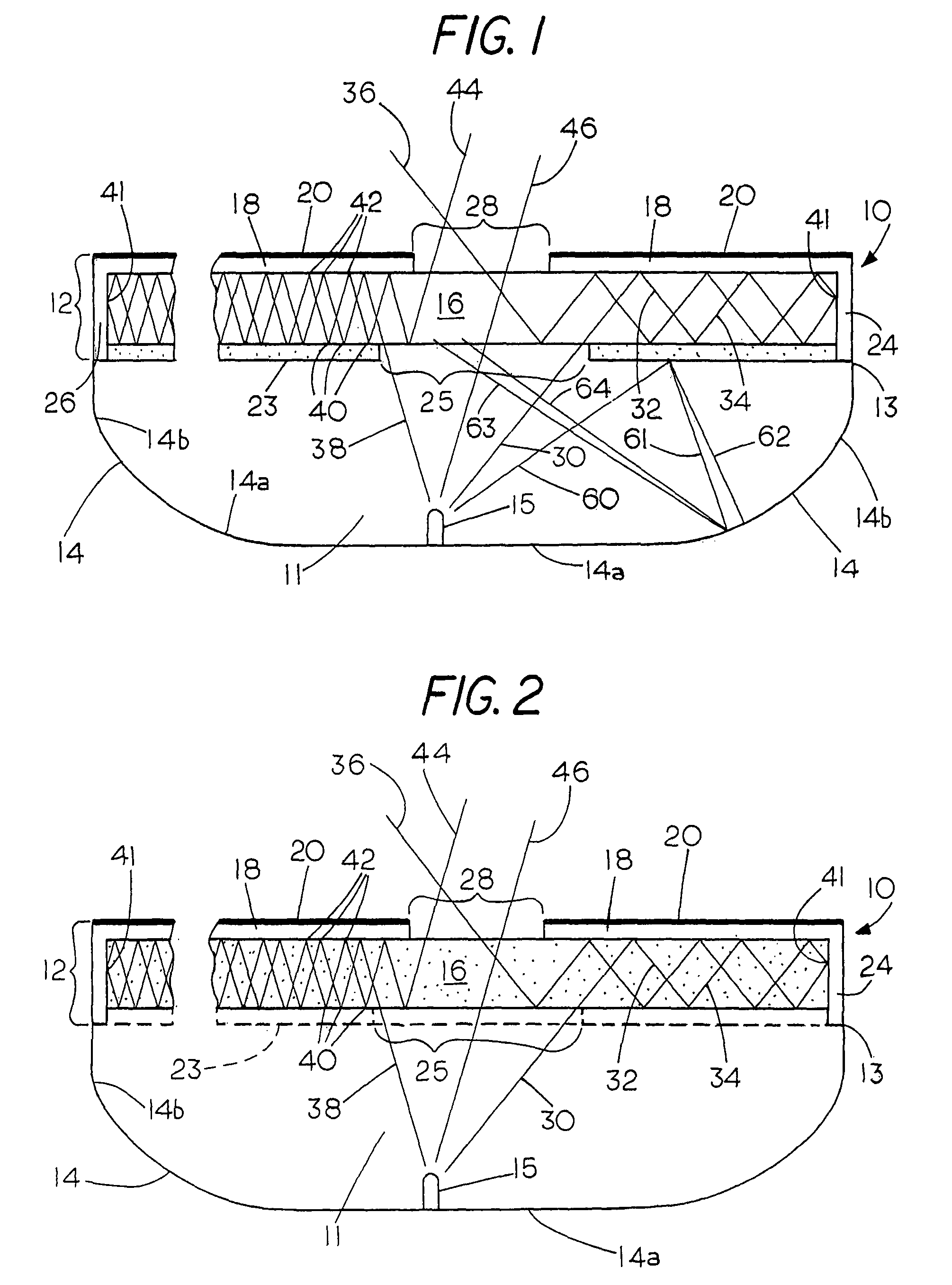
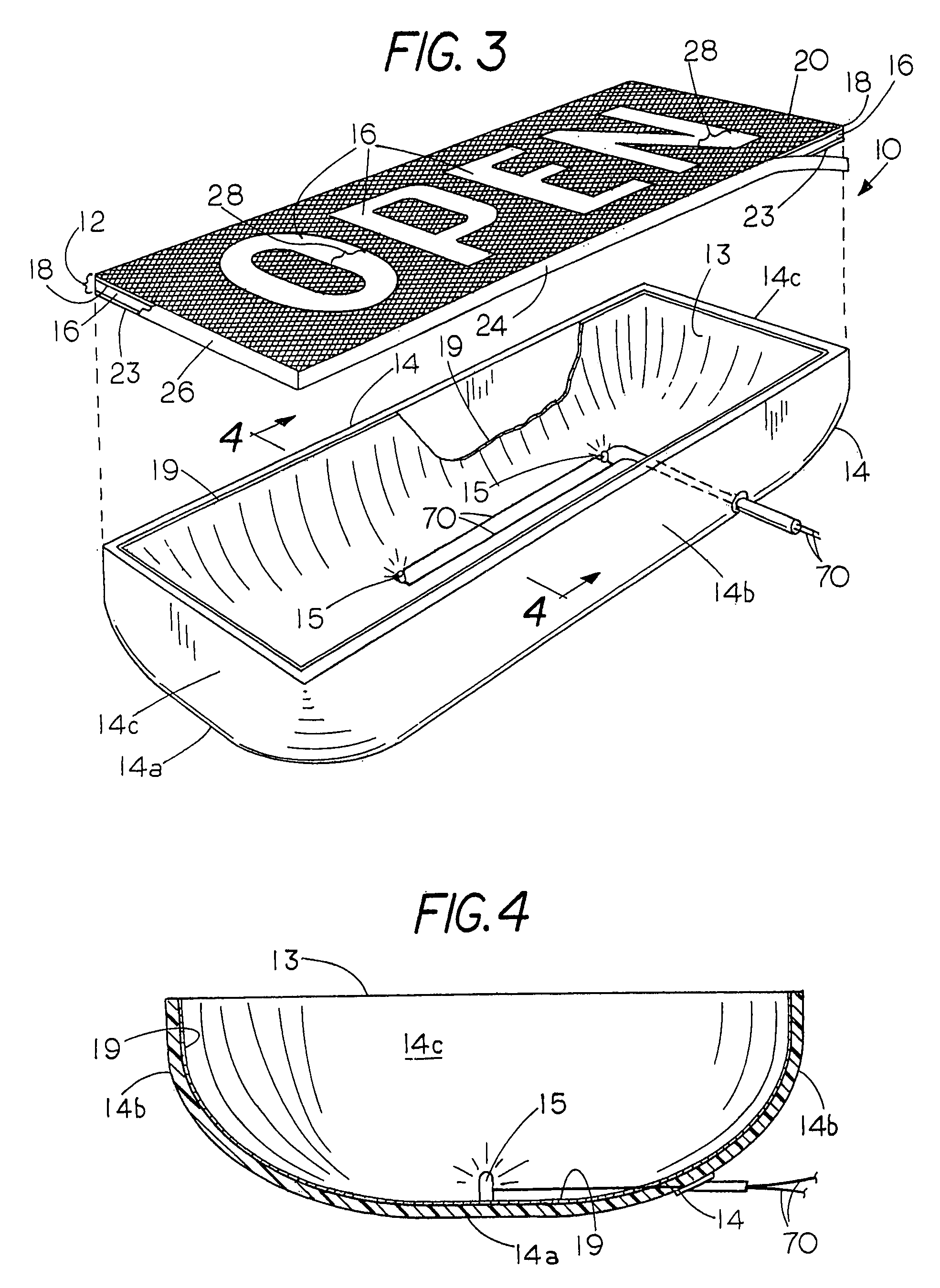
[0027]Refer now to FIGS. 1 and 2 which illustrate the major components of the invention and include light rays to show diagrammatically the operation of the invention. In FIG. 1 a backlit display sign indicated generally by the numeral 10 includes a sign front face cover element 12 on which a visible display is seen from above in this case and a rear sign enclosure element 14 having an open wide mouth 13 which is covered by the face cover element 12 to define a light chamber 11 between them that contains a light source, in this case an LED 15 of a suitable commercially available type such as a top-emitting LED, for example a Lumileds Luxeon Star I, III and Rebel LED for emitting white, bluish white, or colored light as desired. Commercially available LED's can be selected to provide desired color. The LED 15 typically provides more than 20 lumens.

[0028]The front face cover 12 includes an optically transmissive self-supporting rigid sheet of transparent acrylic plastic 16 which is su...


PUM


Abstract

A backlit display sign includes a rear sign enclosure element at the back of the sign with a forwardly facing wide mouth opening. Extending across the mouth opening is a front sign element or cover formed from an optically transmissive light guide which extends laterally across the mouth opening of the display. Light diffusing (scattering) reflective layers on the front and rear surfaces of the guide or within the guide itself make the guide a light propagation sustaining channel that serves to funnel light rays laterally and forwardly within itself to an image-producing opening where the light is allowed to be emitted for producing the image of a symbol, letter, number or other indicia that is visible on the front of the display. A light cavity between the front cover and the rear sign enclosure element contains at least one illuminating device, e.g. a light emitting diode (LED), to provide visible illumination that is transmitted from within the light cavity through the guide to the front of the sign. A light reflective layer is provided on the inner surface of the rear sign enclosure to direct rays forwardly. A light tunnel can be supported within the sign to furnish light of a selected color from a second light source within the tunnel to a portion of the sign within the bounds of the light tunnel where the different color is provided than that of the illuminating device used for the rest of the sign.

Description

FIELD OF THE INVENTION[0001]This invention relates to backlit display signs, markers, perimeter lighting, and the like, and to backlit light emitting diode (LED) signs.BACKGROUND OF THE INVENTION[0002]Neon display signs while very bright are expensive to produce and subject to high operating and maintenance costs. The maintenance costs may be as high as 30% or more annually and include glass tube breakage, transformer failure, corrosion, electrical shorts that cause fires, hazardous disposal requirements and other costs. Neon signs in addition operate at from about 3,800 to 15,000 volts. Other kinds of lamps such as high intensity discharge, HID, metal halide lamps are rarely used because replacement lamp cost, short lamp life, high heat inside sign box cavities and hazardous disposal of failed lamps. Florescent lamps have shortcomings similar to HID lamps with the exception of lamp cost. Consequently, light emitting diode (LED) lighting is preferred for use in the present invention...

Claims


Application Information

Patent Timeline
Patent Type & Authority Patents(United States)
IPC IPC(8): G09F13/04
CPCG02B6/005G02B6/006G09F13/04G09F13/14G09F13/22G09F2013/142Y10S362/812
Inventor REILAND, DENNIS J.ROBERTSON, DONALD L.RANDALL, BRIAN J.
Owner ELLUMINEERING
Why Eureka
Try Eureka