Electrically controlled proportional valve

a proportional valve, electric control technology, applied in valve details, valve arrangement, machines/engines, etc., can solve the problems of limited flow resolution, travel distance, and limited flow resolution of resultant flow, so as to improve resolution and resolution performance, the effect of increasing the range of performan

Active Publication Date: 2010-07-06
KELLY EDMUND F
View PDF26 Cites 31 Cited by
  • Summary
  • Abstract
  • Description
  • Claims
  • Application Information

AI Technical Summary

Benefits of technology

[0013]The incorporation of the orbital leaf spring design, as opposed to a radial spring design, offers a larger range of performance, as well as improved resolution. This is due to the circular structure of the orbital leaf springs, such that the total available travel distance of the moment force is not limited to a radial distance from the center of the armature. As shown in U.S. Pat. No. 6,220,569, a radial spring design defines the path of travel of the moment force linearly, from the center of the armature to the outer diameter of the armature support. Alternately, the orbital leaf spring design defines the path of travel of the moment force circularly, along an orbital path distanced from the axis of rotation, or center of the armature. Due to the circular path made available by the orbital leaf spring design, the total available travel distance of the moment force is equivalent to the total available arc length, and so from trigonometry, the arc length may be greater than the radius, or available radial distance, while the radius is limited linearly. Therefore, due to its circular nature, the orbital leaf spring design inherently offers a larger range of travel for the moment force, more numerous moment force positions, and therefore higher resolution performance.
[0014]Another advantage to the incorporation of the orbital leaf spring design, as opposed to a radial spring design, is improved stability of the armature, and therefore improved hysteresis performance. This is due to the orbital travel of the moment force about the axis of rotation, or center of the armature. As mentioned previously, a radial spring design defines the path of travel of the moment force linearly; in

Problems solved by technology

However, in such a configuration the total travel distance of the moment arm, and therefore the resultant flow resolution and ar

Method used


Image

  • Electrically controlled proportional valve
  • Electrically controlled proportional valve
  • Electrically controlled proportional valve

Examples


Embodiment Construction

[0023]The best mode for carrying out the invention is presented in terms of its preferred embodiment, herein depicted within the Figures.

1. Detailed Description of the Figures

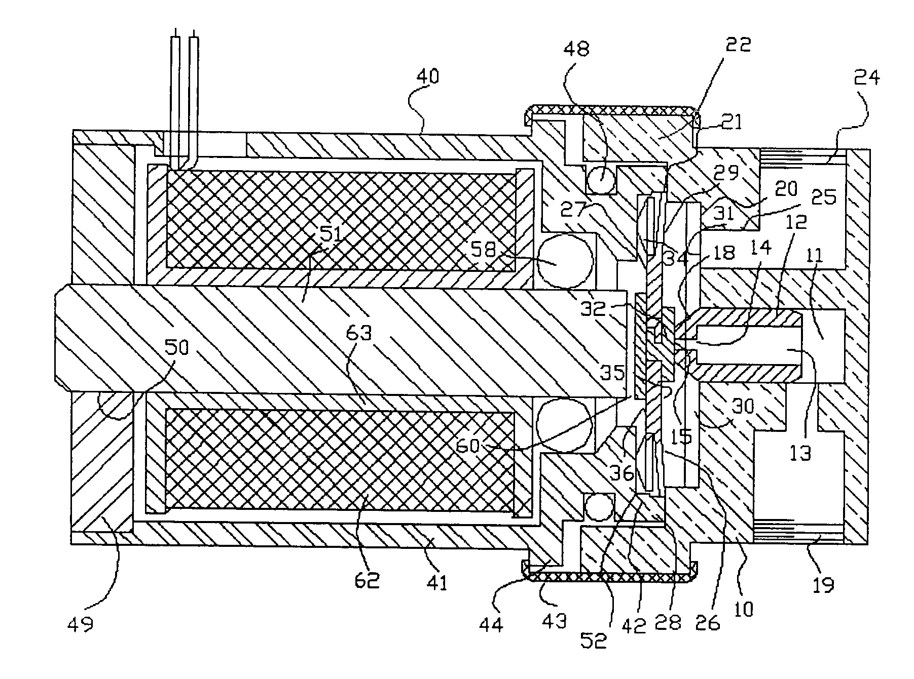
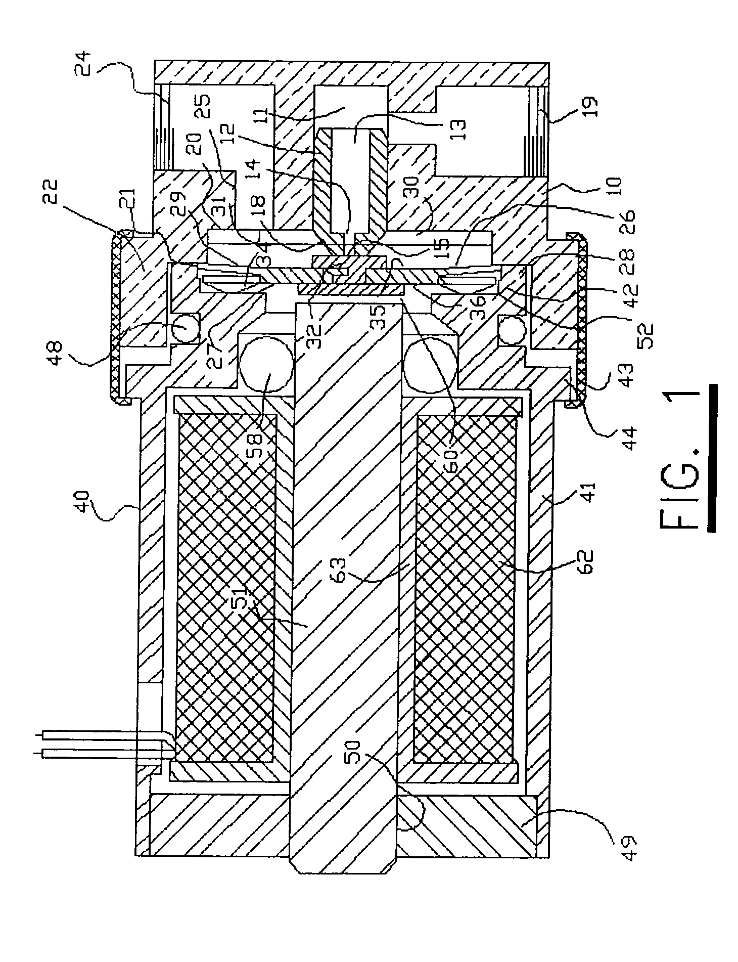
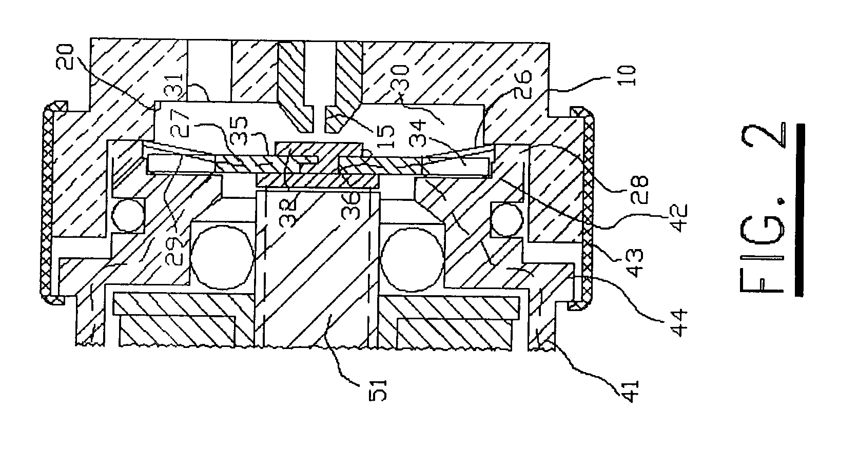
[0024]The valve embodiment illustrated in the drawing includes body structure 10 which is adapted to be received in one end of the internal cavity of the manifold body of valves of the type shown in U.S. Pat. Nos. 3,766,935, 3,786,831, and 6,220,569. Body 10 has a stopped central bore 11, in which is secured an insert 12 that presents an axial first passage 13 that leads through a stepped bore 14 to a first port 15. A tip 18 of small area is presented by insert 12 around first port 15, and forms a small seat for a movable valve element to be described. A bore 19 leads radially through body 10 to the inner end of bore 11, and in use a fluid conduit, not shown, may be coupled to this bore 19. Body 10 is recessed, as at 20, around the projecting tip 18 of insert 12. An external skirt 22 surrounds recess 20, thereb...


PUM


Abstract

An electrically controlled proportional valve provides for precise control of armature movement using an armature which is positioned at the center of the valve by centering leaf springs. The armature is supported and biased axially by angled leaf springs that support the armature in an orbital fashion. These angled orbital leaf springs support the armature for elastic movement in the axial direction, and hold it biased against a first port, so that the armature functions as a valve element, which normally closes that port. A magnet coil is positioned so that when an electrical current passes through the coil, it exerts a force on the armature which overcomes the bias of the orbital leaf springs and draws the armature away from the first port and toward the magnet coil.

Description

BACKGROUND OF THE INVENTION[0001]1. Field of the Invention[0002]The present invention relates to a proportional valve and, more particularly, to an electrically controlled proportional valve having a movable valve element which is in the form of an orbital leaf spring valve element, and which also comprises the armature operated by the electromagnet coil.[0003]2. Description of the Related Art[0004]Proportional valves are useful in pneumatic control circuits, and may be used, for example, to control precise gas flow through the valve. A search of the prior art did not disclose any patents that read directly on the claims of the instant invention; however, of considerable relevance is U.S. Pat. No. 6,220,569 to Kelly which shows an electrically operated pneumatic valve in which a combination magnetically operated armature and an angled surface of the valve case are biased so as to proportionally control flow. However, in such a configuration the total travel distance of the moment ar...

Claims


Application Information

Patent Timeline
IPC IPC(8): F16K31/02
CPCF16K31/0655
Inventor KELLY, EDMUND F.
Owner KELLY EDMUND F
Why Eureka
Try Eureka