Compact robot vacuum cleaner

a robot vacuum cleaner and compact technology, applied in the field of vacuum cleaners, can solve the problems of deteriorating cleaning performance, bulky robot cleaners, and low suction efficiency of small-size suction motors compared to general-purpose suction motors

Active Publication Date: 2010-07-06
SAMSUNG GWANGJU ELECTRONICS CO LTD
View PDF20 Cites 45 Cited by
  • Summary
  • Abstract
  • Description
  • Claims
  • Application Information

AI Technical Summary

Benefits of technology

[0011]An aspect of the present invention is to solve at least the above problems and / or disadvantages and to provide at least the advantages described below. Accordingly, an aspect of the present invention is to provide a robot cleaner having compact size.
[0013]In order to achieve the above-described aspects of the present invention, there is provided a robot cleaner that has a dust collection unit including a cyclone part generating an ascending rotary air current from the dust-laden air being drawn in through a lower part thereof, separating the dust from the air using a centrifugal force, and discharging the dust-separated air to the lower part through a center part; and a collection part surrounding the cyclone part to receive the dust being centrifugally separated. According to this structure, the height of the robot cleaner can be reduced, thereby providing a compact robot cleaner.
[0016]Accordingly, since the rotative force is exerted through the spiral path to the air being drawn in through the suction path, a high average suction force as well as a high initial suction force can be guaranteed. Also, the size of the robot cleaner can be slimed by adopting the cyclone part having the low height.
[0017]The dust collection unit may further comprise a cover removably connected to an upper part thereof to open and close the cyclone part and the collection part. The cover may comprise a concave portion disposed on the cover at a position corresponding to the inner canister of the cyclone part and recessed toward the inner canister, to decrease volume of an upper end portion of the inner canister for favorable discharge of the air dust-separated by the cyclone part; and one or more handles mounted in the concave to help withdrawal of the dust collection unit from the cleaner body. The one or more handles may be pivotably mounted by one ends thereof by a fixing projection formed in the concave.

Problems solved by technology

However, when the dust bag is full or the dust receptacle is blocked, the suction force drops considerably, accordingly deteriorating cleaning performance.
Also, conventional robot cleaners generally use a rechargeable battery, which supplies limited amounts of electric power, and accordingly uses a small-size suction motor consuming relatively less power to maintain compact size of the robot cleaner.
However, such a small-size suction motor has lower suction efficiency than general suction motors.
However, since this structure increases the volume of the cyclone unit, the robot cleaner is bulky and not compact.
This structure also makes it hard to compactly design the robot cleaner because the dust receptacle connected to a lower part of the cyclone unit increases the height of dust collection unit.
The long dust suction path causes loss of energy due to friction with the rotating air current, thereby seriously deteriorating the initial suction force.
However, this increases weight of the robot cleaner.
If the robot cleaner climbs an obstacle, such as a doorsill, the robot cleaner may fall down and be damaged.

Method used


Image

  • Compact robot vacuum cleaner
  • Compact robot vacuum cleaner
  • Compact robot vacuum cleaner

Examples


Embodiment Construction

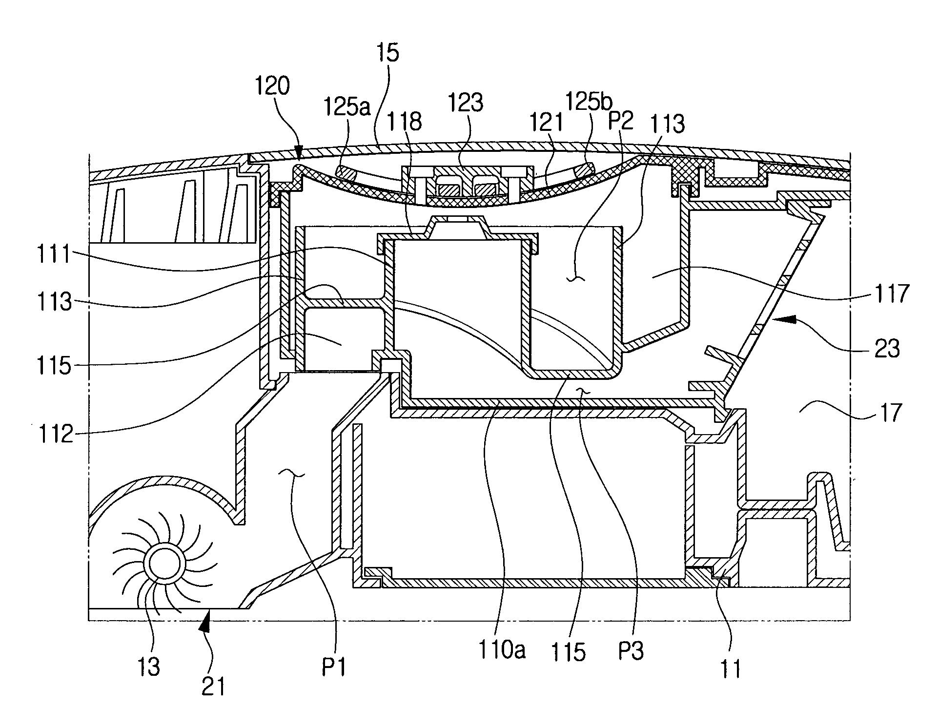
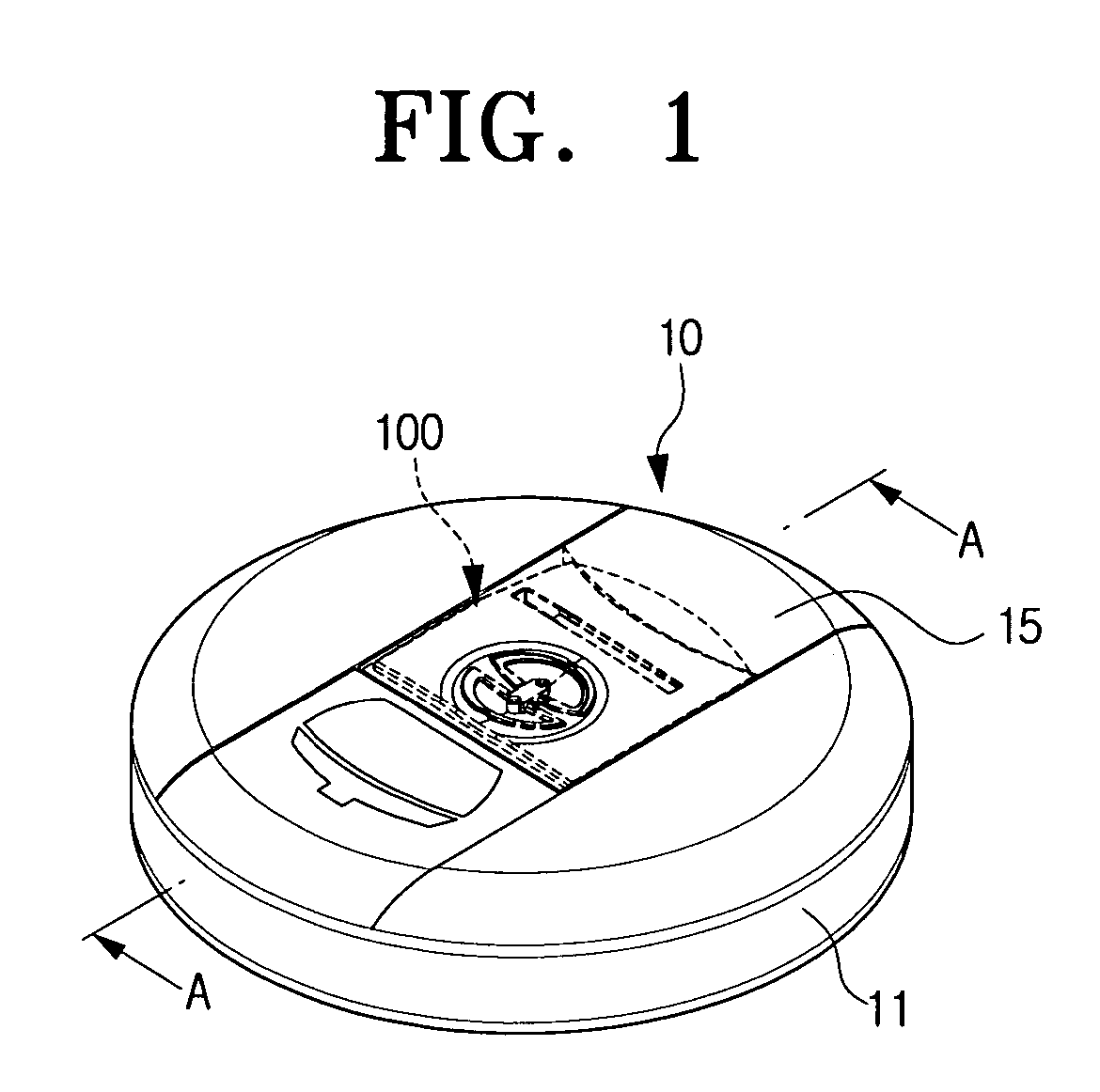
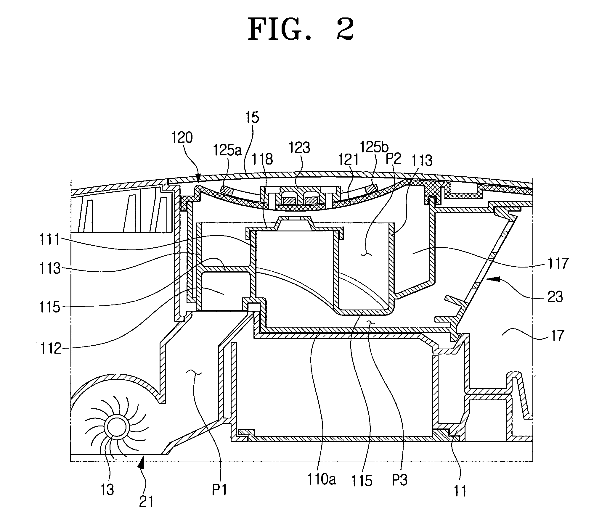
[0028]Hereinafter, a robot cleaner according to an embodiment of the present invention will be described in detail with reference to the accompanying drawing figures.

[0029]In the following description, same drawing reference numerals are used for the same elements even in different drawings. The matters defined in the description such as a detailed construction and elements are nothing but the ones provided to assist in a comprehensive understanding of the invention. Thus, it is apparent that the present invention can be carried out without those defined matters. Also, well-known functions or constructions are not described in detail since they would obscure the invention in unnecessary detail.

[0030]Also, description about general component parts of a robot cleaner, for example, a driving unit for automatic traveling, a sensor unit, and a control unit for conducting the driving unit and the sensor unit, will be omitted herein. Instead, the present invention will be described featuri...


PUM

PropertyMeasurementUnit
forceaaaaaaaaaa
volumeaaaaaaaaaa
rotating angleaaaaaaaaaa

Abstract

A robot cleaner that has a dust collection unit with a cyclone part generating an ascending rotary air current from the dust-laden air being drawn in through a lower part thereof, separating the dust from the air using a centrifugal force, and discharging the dust-separated air to the lower part through a center part, and a collection part surrounding the cyclone part to receive the dust being centrifugally separated.

Description

CROSS-REFERENCE TO RELATED APPLICATIONS[0001]This application may relate to co-pending, commonly owned U.S. patent application Ser. Nos. 10 / 753,322, filed Jan. 9, 2004, and 10 / 887,840, filed Jul. 12, 2004, the subject matter of each of which is incorporated herein by reference.REFERENCE TO RELATED APPLICATION[0002]This application claims benefit under 35 U.S.C. §119(a) of Korean Patent Application No. 2005-125664, filed Dec. 19, 2005, the entire contents of which are incorporated herein by reference.FIELD OF THE INVENTION[0003]The present invention relates to a vacuum cleaner. More particularly, the present invention relates to a robot vacuum cleaner that adopts a cyclone structure.BACKGROUND OF THE INVENTION[0004]Conventional robot cleaners generally comprise a dust suction unit, which includes a suction port and a rotary brush, a suction motor which provides a vacuum source, a sensor unit which includes an obstacle sensor and a distance sensor measuring a traveling distance and lo...

Claims


Application Information

Patent Timeline
Patent Type & Authority Patents(United States)
IPC IPC(8): B01D45/00A47L9/10A47L5/00
CPCA47L5/28A47L9/1608A47L9/1683A47L2201/00Y10S15/03A47L9/16A47L9/00
Inventor OH, JANG-KEUNLEE, HAK-BONG
Owner SAMSUNG GWANGJU ELECTRONICS CO LTD
Why Eureka
Try Eureka