Blind via capture pad structure

Active Publication Date: 2010-07-06
AMKOR TECH SINGAPORE HLDG PTE LTD
View PDF140 Cites 8 Cited by
  • Summary
  • Abstract
  • Description
  • Claims
  • Application Information

AI Technical Summary

Benefits of technology

[0010]As the focused laser beam is moved in straight lines rapidly, the laser ablation process used to form the capture pad is fast and thus performed at a minimal cost.
[0011]Further, the total area of the capture pad is less than a circular capture pad having a diameter equal to the length of the li

Problems solved by technology

However, the laser ablation process used to form the circular capture pad opening is rela

Method used


Image

  • Blind via capture pad structure
  • Blind via capture pad structure
  • Blind via capture pad structure

Examples


Example

[0034]In the following description, the same or similar elements are labeled with the same or similar reference numbers.

DETAILED DESCRIPTION

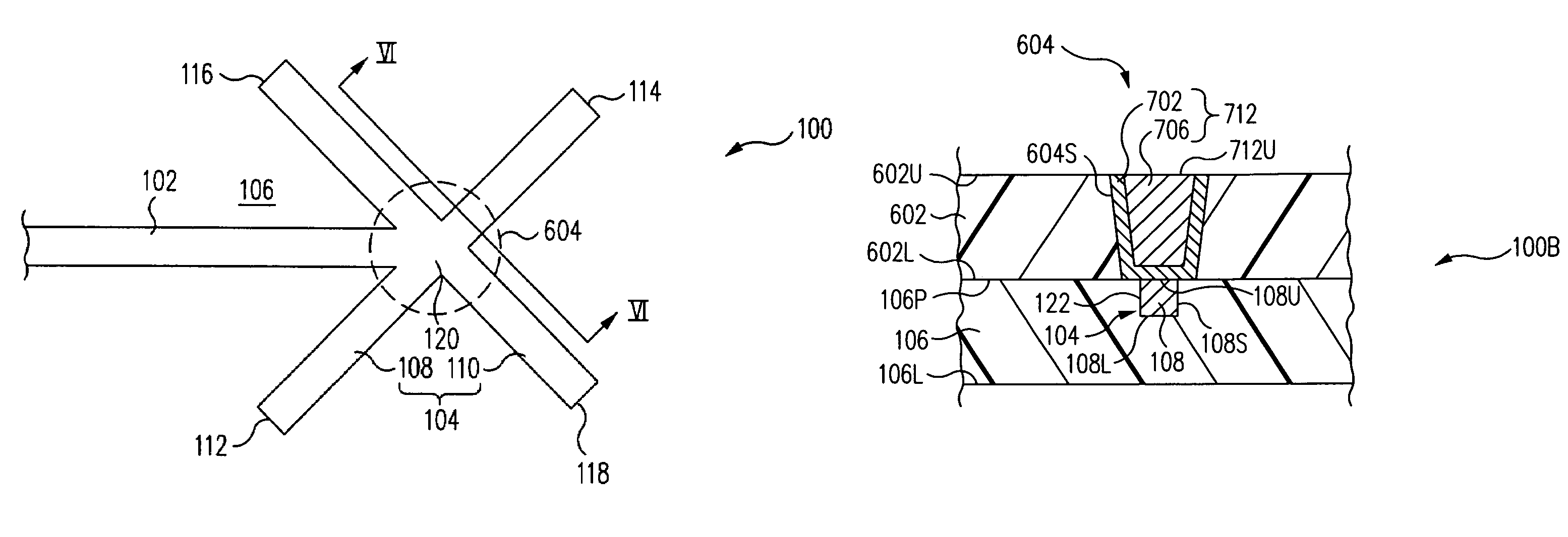
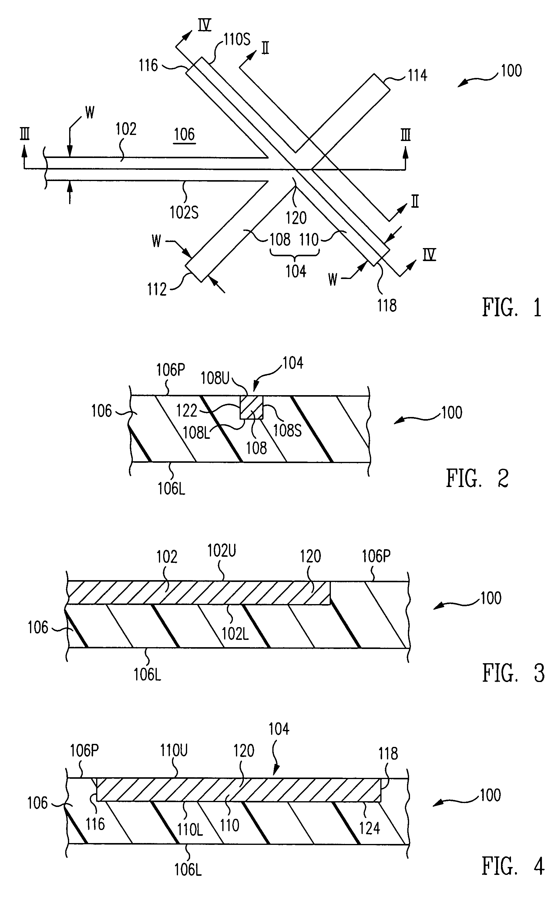
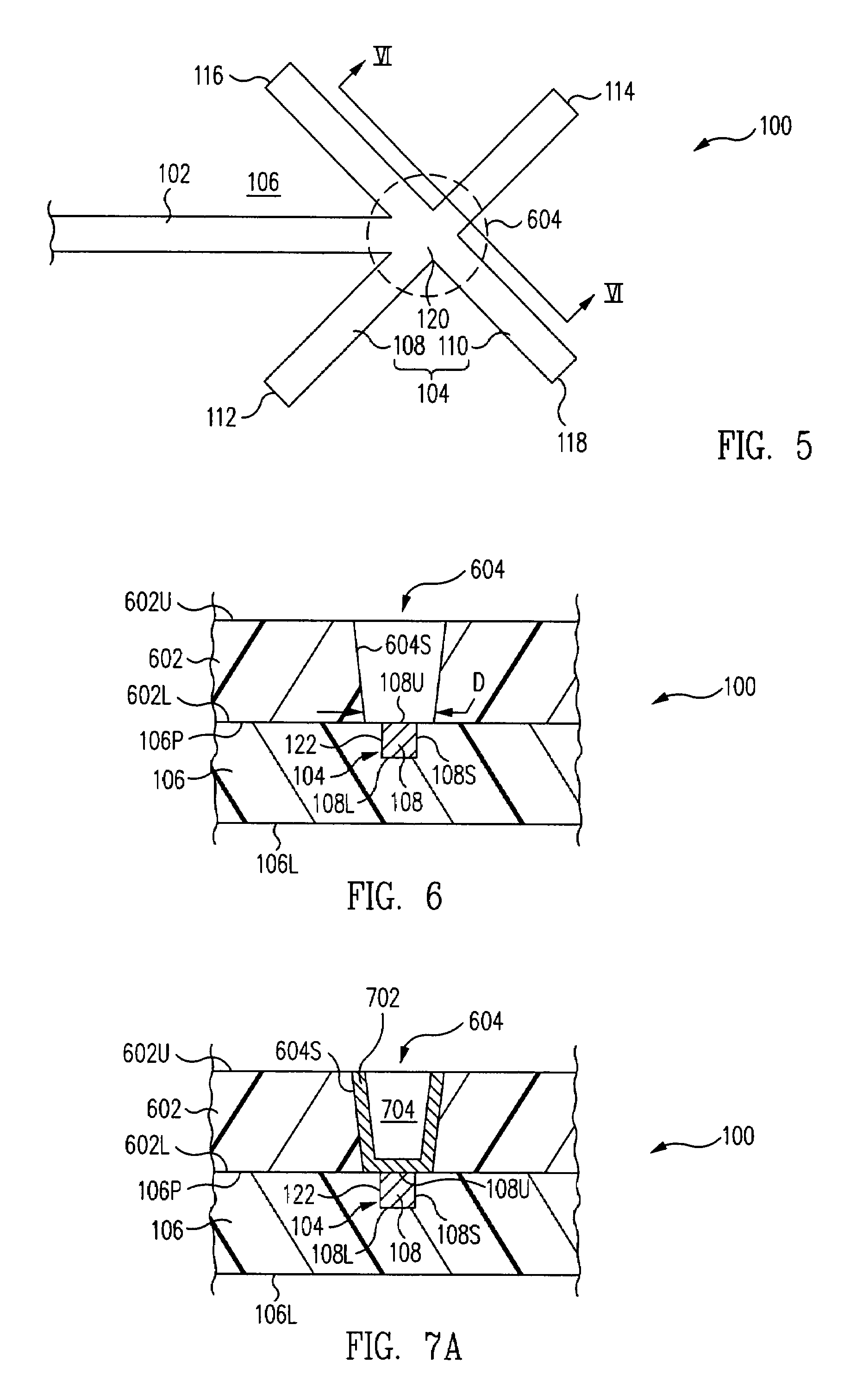
[0035]In accordance with one embodiment, referring to FIGS. 1, 2, 3, and 4 together, a capture pad structure 100 includes a lower dielectric layer 106, a capture pad 104 embedded within lower dielectric layer 106, capture pad 104 comprising a plurality of linear segments 108, 110.

[0036]In accordance with one embodiment, capture pad 104 is formed using a laser ablation process. In accordance with this embodiment, dielectric layer 106 is laser-ablated to form channels therein. More particularly, a focused laser beam is moved linearly, i.e., in straight lines, to form linear channels in dielectric layer 106. These channels are filled with an electrically conductive material to form capture pad 104.

[0037]More particularly, the focused laser beam is moved in a first straight line to form a first channel 122 in dielectric layer 106 in which first line...


PUM

PropertyMeasurementUnit
Lengthaaaaaaaaaa
Dielectric polarization enthalpyaaaaaaaaaa
Electrical conductivityaaaaaaaaaa

Abstract

A capture pad structure includes a lower dielectric layer, a capture pad embedded within the lower dielectric layer, the capture pad comprising a plurality of linear segments. To form the capture pad, a focused laser beam is moved linearly to form linear channels in the dielectric layer. These channels are filled with an electrically conductive material to form the capture pad.

Description

BACKGROUND OF THE INVENTION[0001]1. Field of the Invention[0002]The present invention relates generally to substrates for mounting of electronic components. More particularly, the present invention relates to a blind via capture pad structure and method for fabricating the same.[0003]2. Description of the Related Art[0004]In multi-layer substrates, an electrically conductive circular capture pad is formed in a first dielectric layer. The circular capture pad is used to form an electrical connection with an electrically conductive blind via formed through a second dielectric layer mounted to the first dielectric layer.[0005]To compensate for registration errors, the circular capture pad is much larger in diameter than the bottom of the blind via. This guarantees that the bottom of the blind via will be positioned within the diameter of the capture pad insuring electrical connection between the blind via and the circular capture pad.[0006]Laser ablation is used to form the circular ca...

Claims


Application Information

Patent Timeline
IPC IPC(8): H05K1/11
CPCH01L23/49827H05K1/116H01L23/49838H01L21/486Y10T29/49128Y10T29/49171H05K2201/2072Y10T29/49176H05K2201/09563H05K3/0032Y10T29/49169H05K2201/09781Y10T29/49165H05K3/0038H05K3/0035H05K2201/09481H05K2201/09454H01L2224/48091H05K2201/10674H05K2201/09263Y10T428/24917H05K3/429H01L24/48H05K3/045H01L2224/73204H05K3/107H01L2924/01078H05K3/4038H01L2224/73265H01L2924/00014H01L2924/14H01L2924/00H01L2224/45099H01L2224/45015H01L2924/207
Inventor KUO, BOB SHIH-WEI
Owner AMKOR TECH SINGAPORE HLDG PTE LTD
Why Eureka
Try Eureka