Method and apparatus for location determination using mini-beacons

a technology of location method and mini-beacon, which is applied in the direction of transmitter monitoring, receiver monitoring, instruments, etc., can solve the problems of large infrastructure and satellite deployment cost, location method, and ineffective indoor gps, so as to achieve low cost, reduce installation cost, and protect privacy

Inactive Publication Date: 2010-07-06
FUJITSU LTD
View PDF17 Cites 143 Cited by
  • Summary
  • Abstract
  • Description
  • Claims
  • Application Information

AI Technical Summary

Benefits of technology

[0050]In addition, the present invention further includes schemes for calculating which beacon to select, based on various criteria such as received signal strength. The client location is then reported as the location of this associated mini-beacon. The calculation can be accomplished locally by the mobile computing user providing greater privacy protection or by a location server. Further, a specific design for an apparatus that is a low cost, small size and low power radio-frequency beacon, called a mini-beacon, that is based on the IEEE 802.11 wireless local area networking standard in one aspect of the present invention. A similar device based on the IEEE 802.15.1 radio standard or Bluetooth is another aspect of the present invention.
[0051]More particularly, the mini-beacon approach solves the problems of the related art through a combination of the use of low cost mini-beacons and standard communication protocols and standard communication hardware technologies, the mini-beacon deployment and the location calculation procedure. In general, whenever a difficult spatial area needs to be covered, one would simply add additional low-cost, mini-beacon devices. Some of the difficulties that are overcome include: 1) operating with non-line-of-site deployments, 2) collection and maintenance of building signal intensity maps, 3) need for a priori knowledge of building construction materials, 4) need to overcome multipath interference, and 5) need to limit density of mini-beacons. In addition, when implemented as a client solution, the client has a greater degree of control on the dissemination of its location, providing enhanced privacy protection.
[0052]The method of the present invention provides cubicle-level (2-3 meter) resolution, easily, in a noisy radio environment, indoors, without building radio maps. This provides more robust localization in dynamic environments with fewer burdens on the users.

Problems solved by technology

Since there is no one technology that can address all environments and requirements, it is likely that many different determination methods will be needed to support various location aware applications.
Some location-determination schemes can be fully implemented in an isolated client device, such as a GPS navigation device, although there is a large cost in infrastructure and deployment of the satellites.
Each technology has inherent strengths and weaknesses depending on many factors: accuracy, environment (e.g., temperature, pressure, wind, ambient light), power, infrastructure requirements, susceptibility to noise, etc.
GPS is not effective indoors, although new technologies are being introduced that are sensitive enough to operate in many indoor applications.
Two of the main difficulties in indoor location methods are non-line of sight (walls) measurements and multipath due to reflections.
These methods suffer in indoor environments where many obstacles such as walls and furniture contribute to unpredictable radio channel characteristics and multipath interference.
This usually gives better results than triangulation but it requires the user to build the radio map, a process which can take many hours.
Also, if the environment changes, such as new additions of WLAN AP's, this necessitates a remapping effort.
A problem with pattern matching is the time consuming process of building the radio maps.
In addition, if there is a significant change in the environment such as many people or bulky items, then the accuracy may decrease.
There is also a problem with the accuracy and stability of the measurement process on commercially available 802.11b chip sets.
The data access point is used to infer location, and hence the accuracy is limited to placement of the access point.
Again, the installment cost is high, since one needs to construct the floor with sensors beneath.
These techniques all have problems operating in indoor areas.
Some also require compilation of a large attribute database which is a tedious and time consuming process.
There also are the problems of relating distance to signal strength or other attributes in a general fashion.
This is a complex and difficult task due to the internal structure of interior spaces.
Additional problems in related art include: 1) difficulty of system deployment and operation, 2) use in indoor environments as well as outdoor areas, 3) privacy control by client (target) with regard to disbursement of location data, 4) high total cost of operation due to device and infrastructure requirements, and 5) collection and maintenance of calibration data or radio maps when environment changes.

Method used


Image

  • Method and apparatus for location determination using mini-beacons
  • Method and apparatus for location determination using mini-beacons
  • Method and apparatus for location determination using mini-beacons

Examples


Embodiment Construction

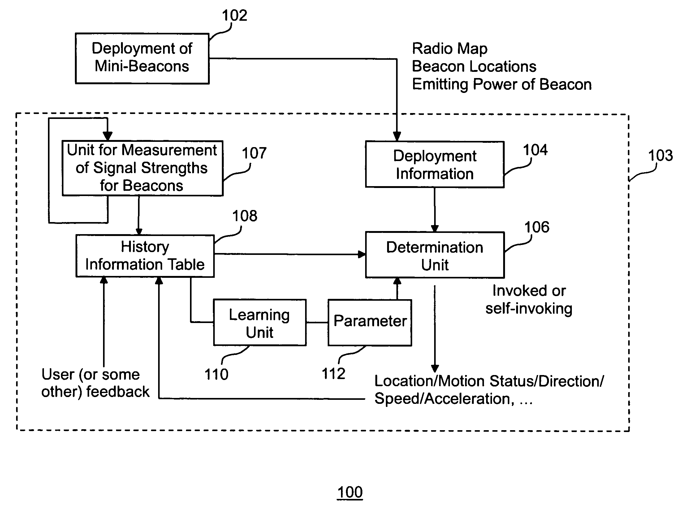
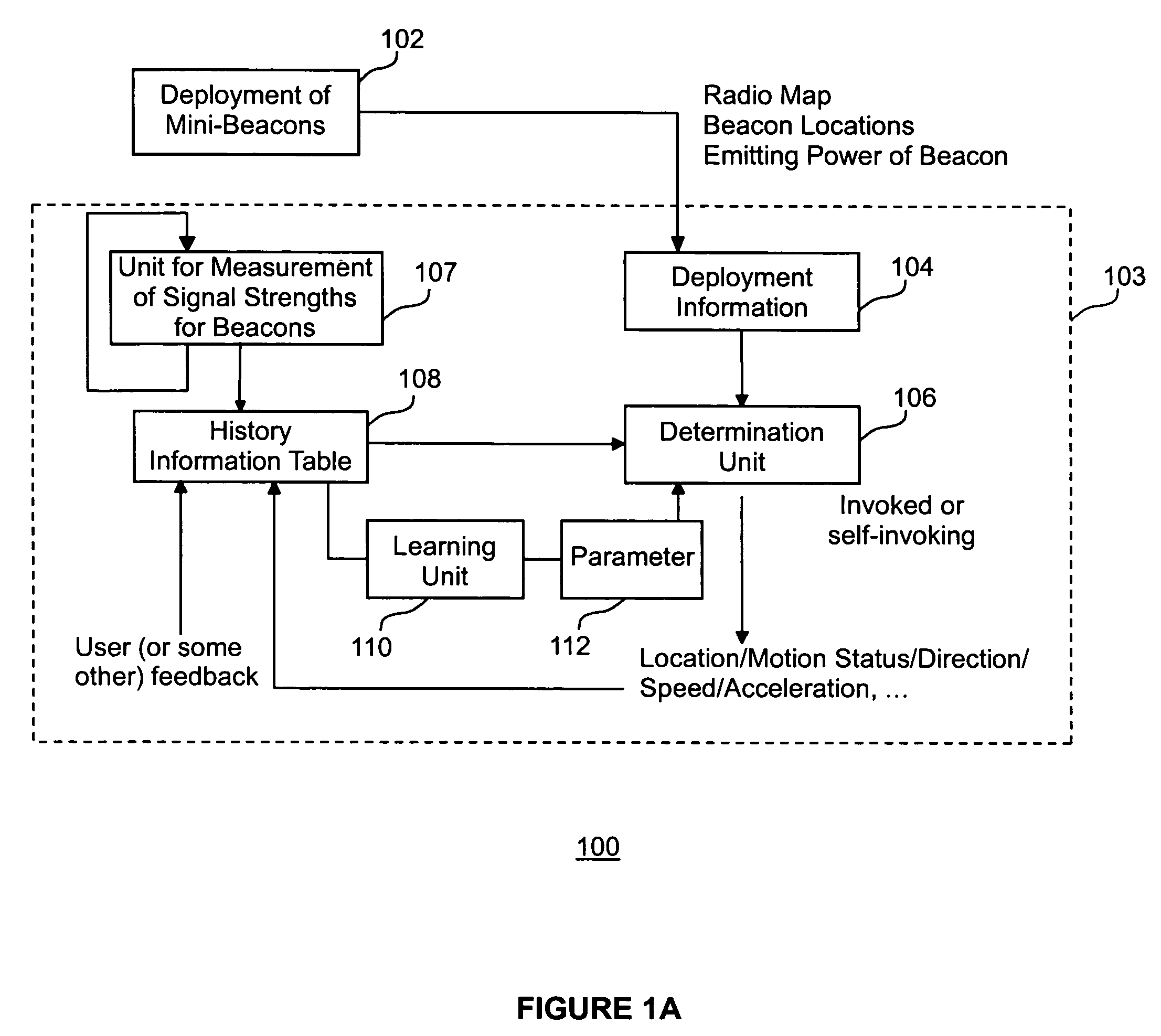
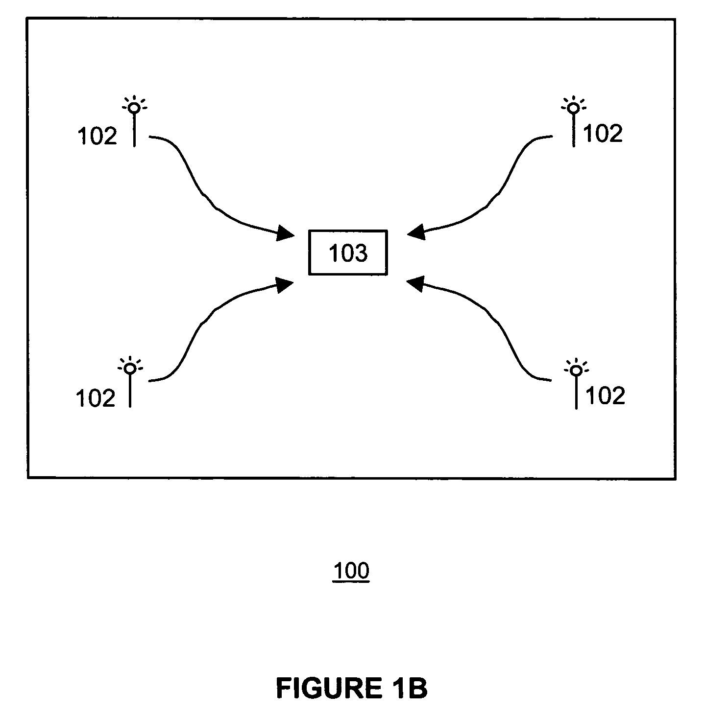
[0071]The present invention includes a basic location-determination apparatus, referred to as a mini-beacon apparatus that operates in conditions in which there is nearly-direct line-of-sight between a desired beacon and the client (or target device, such as a laptop computer or other stationary or hand-held device). A mini-beacon radiates a signal and this signal can be any form of wave for which the intensity can be measured at a target receiver. A client target device with a receiver for the signals will use a procedure based on the measured signal intensities from each beacon within range to determine proximity to the nearest beacon. The mini-beacons are intended to be used in local applications, such as determining in which room or cubicle a target client is currently located. The mini-beacon apparatus may include a 2-way communication device so that a beacon signal is transmitted in response to a request transmitted from a client. A mini-beacon device can also be a transmit-on...


PUM


Abstract

A system and method uses wireless communication devices as beacons to determine the relative location of another target wireless communication device. The beacons transmit identifying information that the target device can use to determine the identity of the beacon. The target device can measure the received intensity of the beacon transmissions and determine an associated beacon that best satisfies a specified criteria (e.g., largest signal strength) using a procedure of the present invention that discriminates between multiple beacons.

Description

CROSS-REFERENCE TO RELATED APPLICATIONS[0001]This application is related to, and claims the benefit of priority to, U.S. Provisional Application No. 60 / 503,878, filed Sep. 22, 2003, the contents of which are incorporated herein by reference.BACKGROUND OF THE INVENTION[0002]1. Field of the Invention[0003]The present invention generally relates to a system and method of using wireless communication devices as beacons to allow a target wireless communication device to determine its location, and, more particularly, the present invention relates to using a collection of beacon devices that communicate using a wireless channel and a common protocol with a target device using this channel and protocol.[0004]2. Description of the Related Art[0005]In mobile computing, the location of the user becomes a fundamental parameter in many applications and services. The ability to automatically and accurately obtain the location of a user or other communicating devices in a wireless networked envir...

Claims


Application Information

Patent Timeline
Patent Type & Authority Patents(United States)
IPC IPC(8): H04W24/00G01S1/04G01S1/68G01S5/02G01S19/10G01S19/21G01S19/46H04B17/00H04W16/28H04W64/00
CPCG01S5/0294H04B17/27G01S1/68G01S1/042
Inventor MASUOKA, RYUSUKEAVANCHA, SASIKANTHTHAKKAR, SOHILAGRE, JONATHAN
Owner FUJITSU LTD
Why Eureka
Try Eureka