
Indoor unit in air conditioner

a technology for indoor units and air conditioners, which is applied in the field of indoor units of air conditioners, can solve the problems of limited indoor unit inside construction, poor user experience, and inability to quickly perform air conditioning for an entire indoor space, and achieve the effects of convenient mounting, improved air suction and discharge methods, and improved structure for constructing indoor units

Inactive Publication Date: 2010-07-13
LG ELECTRONICS INC
View PDF17 Cites 13 Cited by
  • Summary
  • Abstract
  • Description
  • Claims
  • Application Information

AI Technical Summary

Benefits of technology

This design enhances airflow efficiency, allows for convenient installation without spatial limitations, and provides a stronger, simpler structure with increased cooling capacity compared to similar-sized units, improving user convenience and cooling performance.

Problems solved by technology

However, it is not good for the user to use the typical wall mount type indoor unit having the above-mentioned structure because the suction hole is formed at the upper side and the discharge hole is formed at the bottom.
In detail, the drawback is that the air conditioning is not rapidly performed for an entire indoor space because the discharging air is blown only in downward direction.
Further, an inside construction of the indoor unit is limited.
For example, since a cross flow fan is installed in the related art indoor unit, a flow rate is restricted and the indoor unit has a large size because the cross flow fan occupies large portion of the indoor unit.

Method used


Image

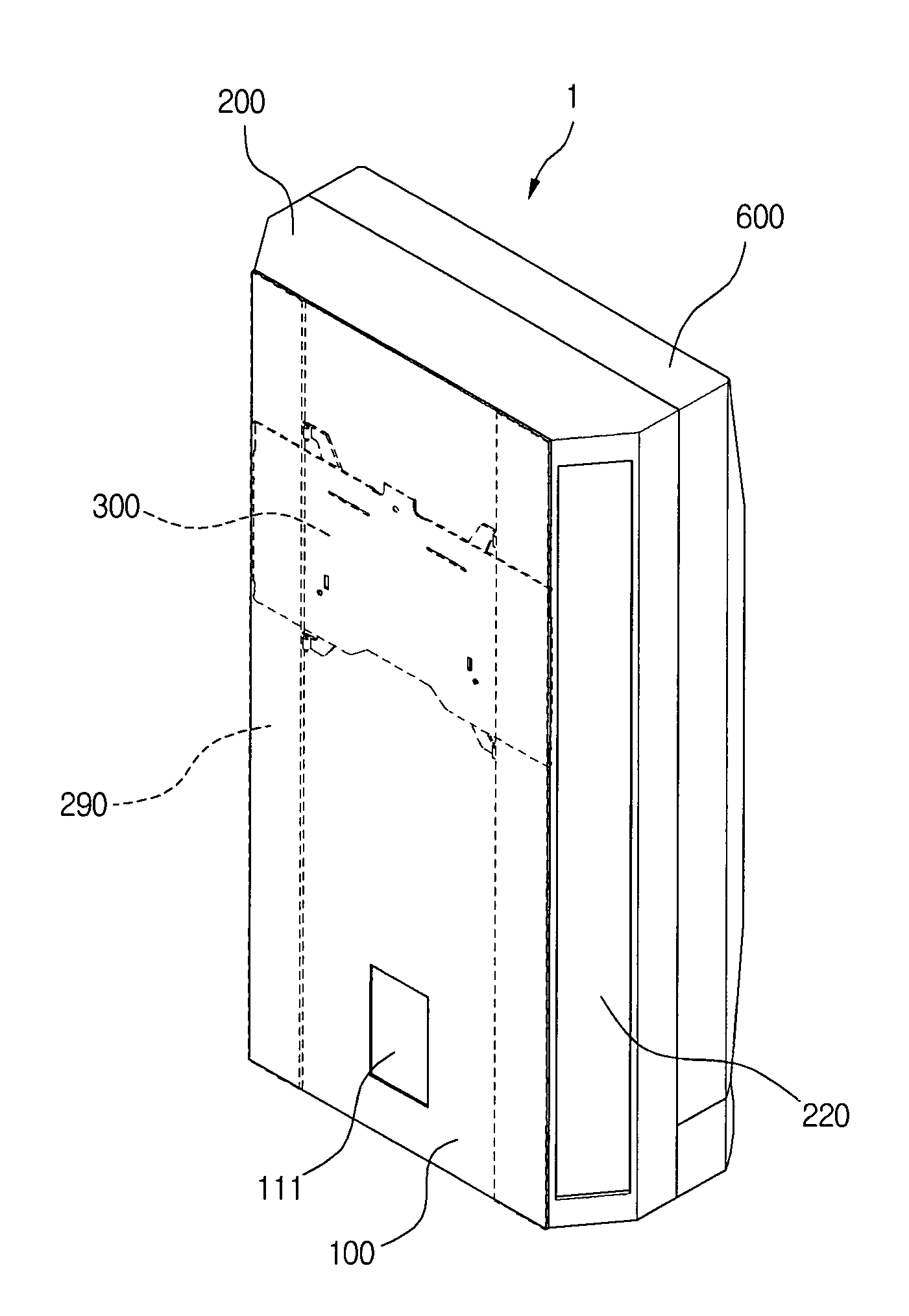
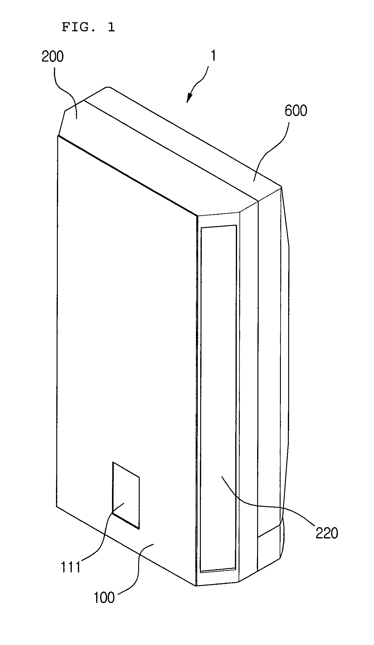
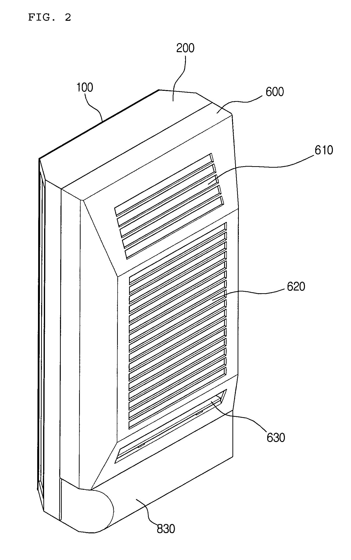
  • Indoor unit in air conditioner
  • Indoor unit in air conditioner
  • Indoor unit in air conditioner

Examples


Embodiment Construction

[0275]An indoor unit of an air conditioner of the present invention has been described and illustrated herein with reference to the preferred embodiments thereof, it will be apparent to those skilled in the art that various modifications and variations can be made therein without departing from the spirit and scope of the invention. Thus, it is intended that the present invention covers the modifications and variations of this invention that come within the scope of the appended claims and their equivalents.

[0276]There will now be provided a number of embodiments that can be changed without departing from the spirit and scope of the present invention.

[0277]In case a front panel and a front frame are coupled in such a way that they are coupled using a hinge at one side and a hook at the other side, instead of a way of hooking the front panel to the front frame, the repairing work or the like can be more conveniently carried out.

[0278]Further, in case a front panel is provide to cover...


PUM


Abstract

An indoor unit of an air conditioner is provided. The indoor unit has an improved airflow structure, for a rapid air conditioning of the room, a user's convenience, and an efficiency of the air conditioner.

Description

[0001]This Non-provisional application claims priority under 35 U.S.C. §119(a) on Patent Application No(s). 10-2003-0074624 and 10-2004-0026933 filed in Korea, Republic of on Oct. 24, 2003 and Apr. 20, 2004, respectively, the entire contents of which are hereby incorporated by reference.TECHNICAL FIELD[0002]The present invention relates to an indoor unit of an air conditioner, and more particularly, to an air conditioner which has an improved suction and discharge method such that the indoor unit of the air conditioner can have efficient inner structure.BACKGROUND ART[0003]Air conditioning system is an apparatus in which a refrigerant performs a refrigerant cycle including compression, condensation, expansion, and evaporation, in order to control the temperature of certain space according to user's desire. When the air conditioning system is operated to lower the temperature of the certain space, the air conditioning system is used as a cooling system. On the other hand, when the ai...

Claims


Application Information

Patent Timeline
Patent Type & Authority Patents(United States)
IPC IPC(8): F25D23/12F24F1/032F24F13/20F24F13/30
CPCF24F1/0007F24F1/0014F24F13/20F24F2013/205F24F2001/0048F24F1/0057F24F1/032
Inventor BAE, JAE BUEM
Owner LG ELECTRONICS INC
Learn More