Swiveling device for a bell crank fork

a technology of swiveling device and bell crank fork, which is applied in the direction of mechanical equipment, couplings, transportation and packaging, etc., can solve the problems of excessive space in small housings, and achieve the effect of reducing the lateral spatial requirement and obtaining the greatest space saving

Active Publication Date: 2010-07-13
SN DETUDE & DE CONSTR DE MOTEURS DAVIATION S N E C M A
View PDF11 Cites 36 Cited by
  • Summary
  • Abstract
  • Description
  • Claims
  • Application Information

AI Technical Summary

Benefits of technology

[0020]The surface which provides the tight fit with the portion of the rod may belong to a bushing engaged in one of the lug bores of the fork. Such a bushing often has the advantage of contributing to the retention of the internal ring in the axial portion.
[0023]The invention is characterized by specific assembly means allowing blocking in rotation, which consist of a pair of planar facets opposing one another, one thereof being made at the bottom of an indentation of one of the lugs of the fork. The other facet is made, according to the embodiments, on a head of the rod, on one of the bushings, or on a circular collar positioned at one polar end of the lower ring, to hold one or other of these parts in rotation. One significant advantage of these pairs of facets is the volume which is saved, since no additional part is required and this arrangement involves nesting of the existing parts, with no protuberance relative to the designs where it does not exist. It is also reliable and durable.
[0026]Certain arrangements of the assembly make it possible to reduce further the lateral spatial requirement by limiting the lengths projecting beyond the fork which remain after the elimination of the screw and nut system. It is in this manner that when the rod comprises a head, it may be housed in an indentation on the external face, or comprise a truncated shape being forced into a conical recess of the lug of the fork. In other designs, the rod comprises a head and one of the fork lugs comprises a recess into which the head is partially forced, instead of abutting against the lug of the fork. It is thus a different means from the head of the rod which define the position for blocking the assembly in translation.
[0027]If the rod is forced completely into the bore of the fork lug, the assembly is thus completely incorporated within the fork and the greatest saving in space is obtained.

Problems solved by technology

The ends of the ball and the nut add to the transverse spatial requirement of the device, which may become excessive within small housings.

Method used


Image

  • Swiveling device for a bell crank fork
  • Swiveling device for a bell crank fork
  • Swiveling device for a bell crank fork

Examples


first embodiment

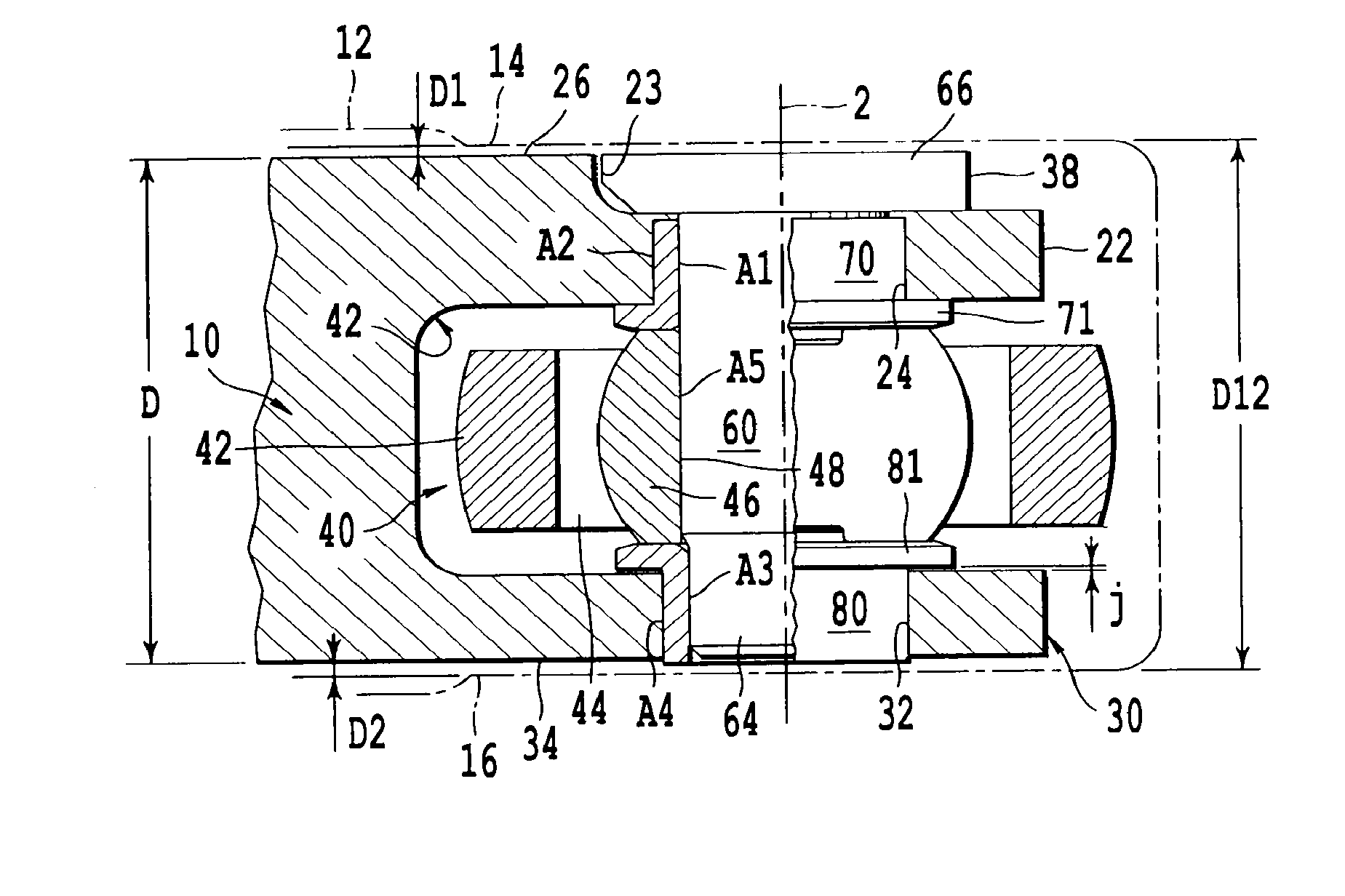
[0070]By referring to FIG. 1, a first embodiment of the assembly 10 according to the invention is shown in section according to a longitudinal plane of symmetry.

[0071]The first fork lug 22 comprises an indentation 38 on its external face opposite the first internal face 14 of the housing 12. This indentation 38 extends from the free end of the first lug 22, passes through the first lug bore 24, extends beyond the first lug bore over a certain distance, and is interrupted when joining the first external face 26 of the fork 20. This indentation 38 defines, on the exterior of the first lug 22, a substantially planar facet 23 which is perpendicular to the longitudinal plane of symmetry (plane of FIG. 1) of the fork 20 and parallel to the assembly axis 2.

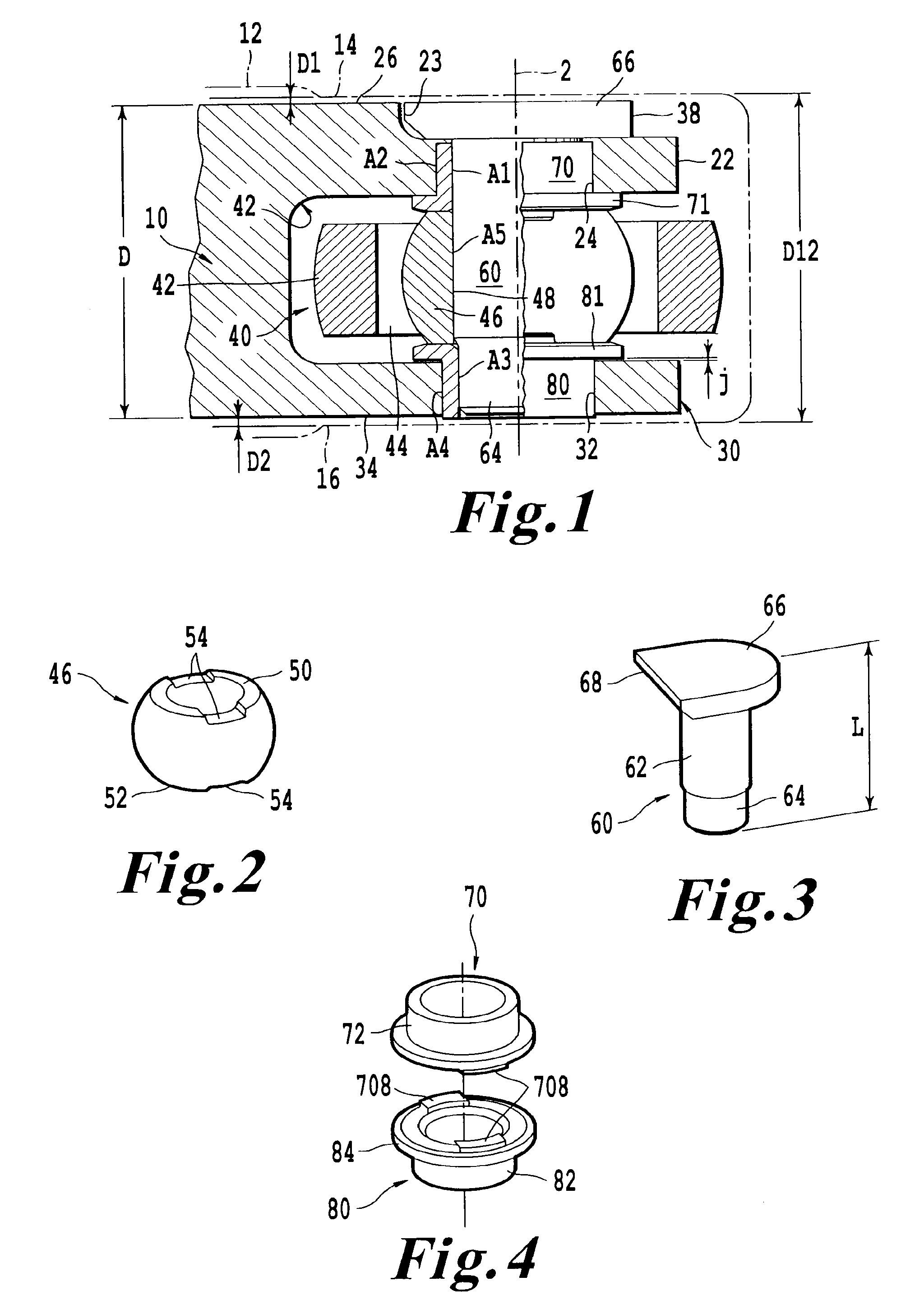
[0072]The internal ring 46 of the swiveling device 40 is shown in perspective in FIG. 2. It has a substantially spherical shape penetrated by a ring bore 48 and cut off at its two poles, defining a first transverse ring face 50 and a sec...


PUM


Abstract

The assembly comprises a fixed fork (10) of which the lugs (22, 30) support a rod (60) onto which a spherical ball is slipped (46) about which a cage (44) and a support (42), of the part which is mobile in rotation, swivel. The maintaining of the axial and angular positions of the spherical ball (46) in the fork is ensured, in particular, by a tight fit (A3) which replaces conventional screw and nut systems positioned at the end of the rod and which project disadvantageously.According to the invention, a pair of planar facets which are opposing and in abutment (including 23) carry out a blocking of one of the assembly pieces in rotation.Application to bell cranks for the transmission of movement, in particular in aircraft engines.

Description

TECHNICAL FIELD[0001]The present invention relates to the field of assemblies of devices swiveling on bell crank forks.[0002]It relates to an assembly of a device swiveling on a bell crank fork.[0003]It also relates to a control system for a variable pitch flow-straightener comprising such an assembly of a device swiveling on a bell crank fork.[0004]It finally relates to an aircraft engine provided with at least one such assembly of a device swiveling on a bell crank fork.PRIOR ART[0005]The assembly of a device swiveling on a bell crank fork is known, for example in the document U.S. Pat. No. 4,174,137. In the known manner, the bell crank fork comprises two parallel lugs, each penetrated by a bore aligned with the bore of the other lug. In a similarly known manner, the swiveling device comprises a spherical internal ring, or ball joint ball, penetrated by a ring bore, which is surrounded by an external ring of spherical shape corresponding to the ball or ball joint cage, itself carr...

Claims


Application Information

Patent Timeline
Patent Type & Authority Patents(United States)
IPC IPC(8): F16C11/06
CPCF16C11/045F16C11/0614Y10T403/32893Y10T403/32221Y10T403/32926Y10T403/32639Y10T403/32704Y10T403/32861F16C2326/43F16C2360/23
Inventor BOURU, MICHEL ANDREETOILE, GERARD JOEL PATRICK
Owner SN DETUDE & DE CONSTR DE MOTEURS DAVIATION S N E C M A
Why Eureka
Try Eureka