Stacked laminate bolted ring segment

a laminated bolted ring segment and laminate technology, applied in the field of ceramic ring segments, can solve the problems of reducing the already low interlaminar properties, t-joints are subject to high interlaminar stresses when loaded, and other out-of-plane features common in laminated structures, so as to improve the interlaminar strength and increase the strength of the assembled structure

Inactive Publication Date: 2010-07-13
SIEMENS ENERGY INC
View PDF28 Cites 38 Cited by
  • Summary
  • Abstract
  • Description
  • Claims
  • Application Information

AI Technical Summary

Benefits of technology

[0004]This present invention provides a ceramic article that may be used as a replacement for one or more metal components used in a turbine system. The ceramic article may include the use of one or more ceramic plates, such as ceramic matrix composite plates, that are reinforced using a strengthening mechanism located in the ceramic article to place the ceramic plates in compression. The strengthening mechanism may reinforce the ceramic plates to increase the strength of the assembled structure in the through thickness direction. The strengthening mechanism may be used within one or more locations of the ceramic article to provide reinforcement and / or improved interlaminar strength.

Problems solved by technology

Other out-of-plane features common in laminated structures, such as T-joints, are also subject to high interlaminar stresses when loaded.
One of the limitations of laminated ceramic matrix composite (CMC) materials, whether oxide or non-oxide based, is that their strength properties are not generally uniform in all directions (e.g. the interlaminar tensile strength is generally less than about 5% of the in-plane strength).
Nonuniform fiber perform compaction in complex shapes and anisotropic shrinkage of matrix and fibers results in delamination defects in small radius corners and tightly curved sections, further reducing the already-low interlaminar properties.
Load carrying capability in a direction normal to the fiber or laminate plane is still severely limited.

Method used


Image

  • Stacked laminate bolted ring segment
  • Stacked laminate bolted ring segment
  • Stacked laminate bolted ring segment

Examples


Embodiment Construction

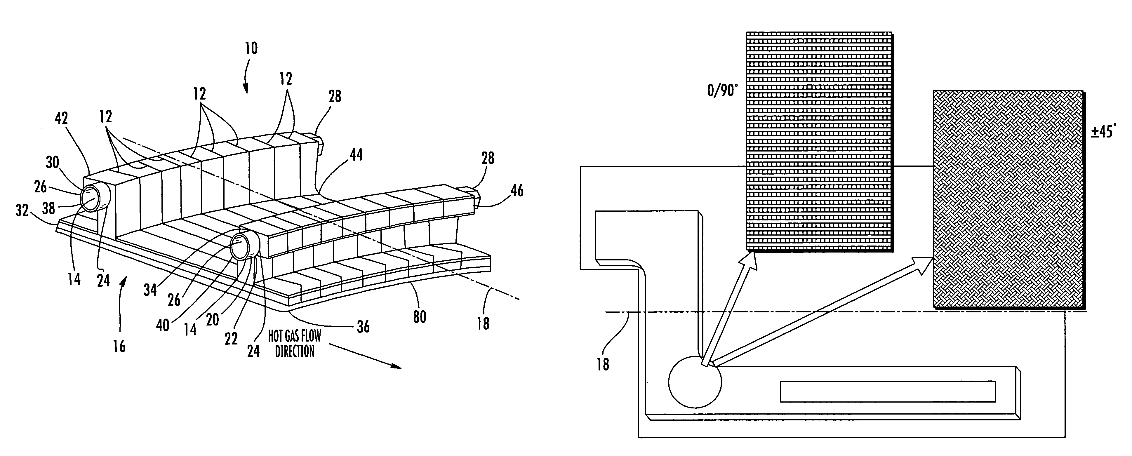
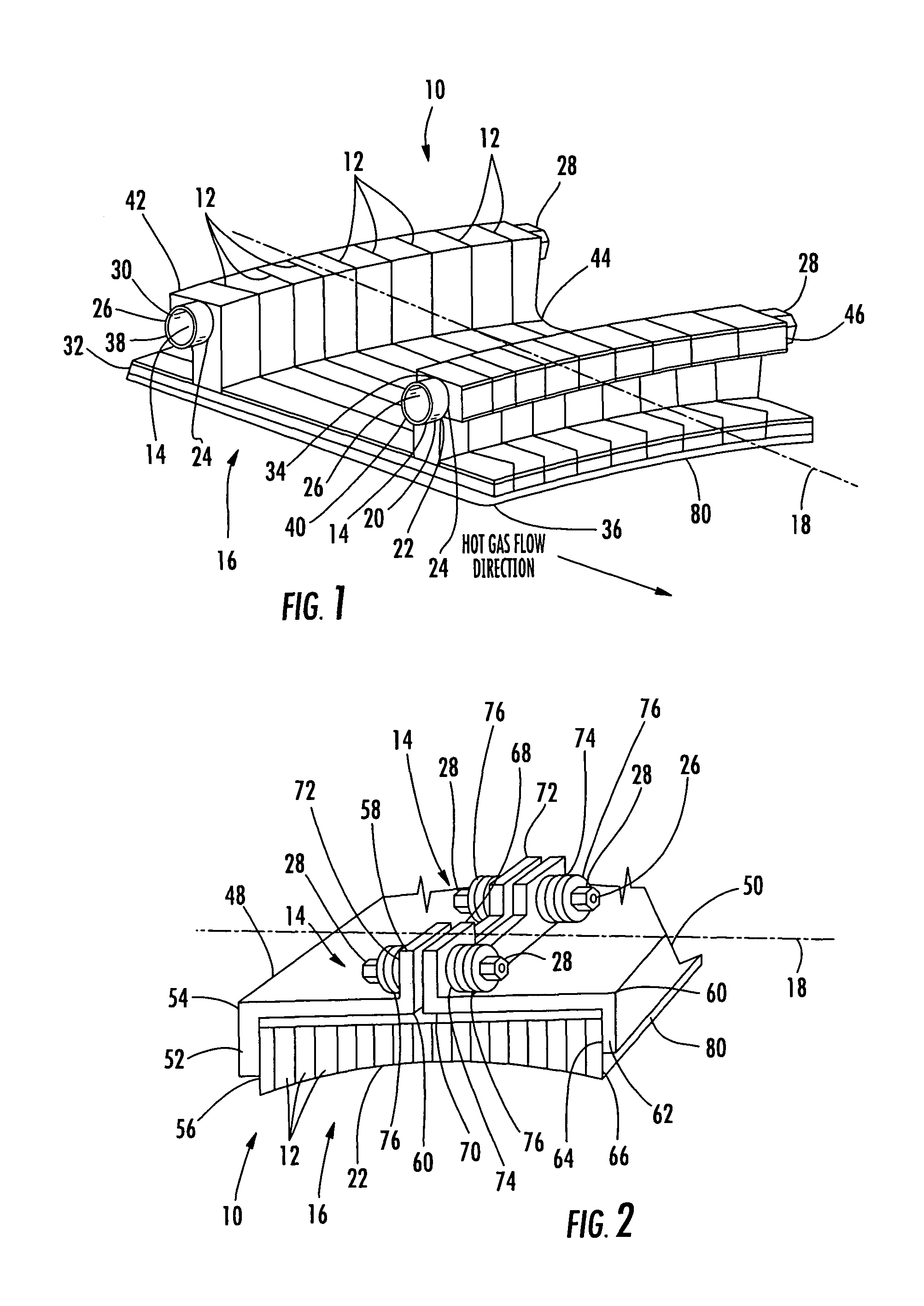
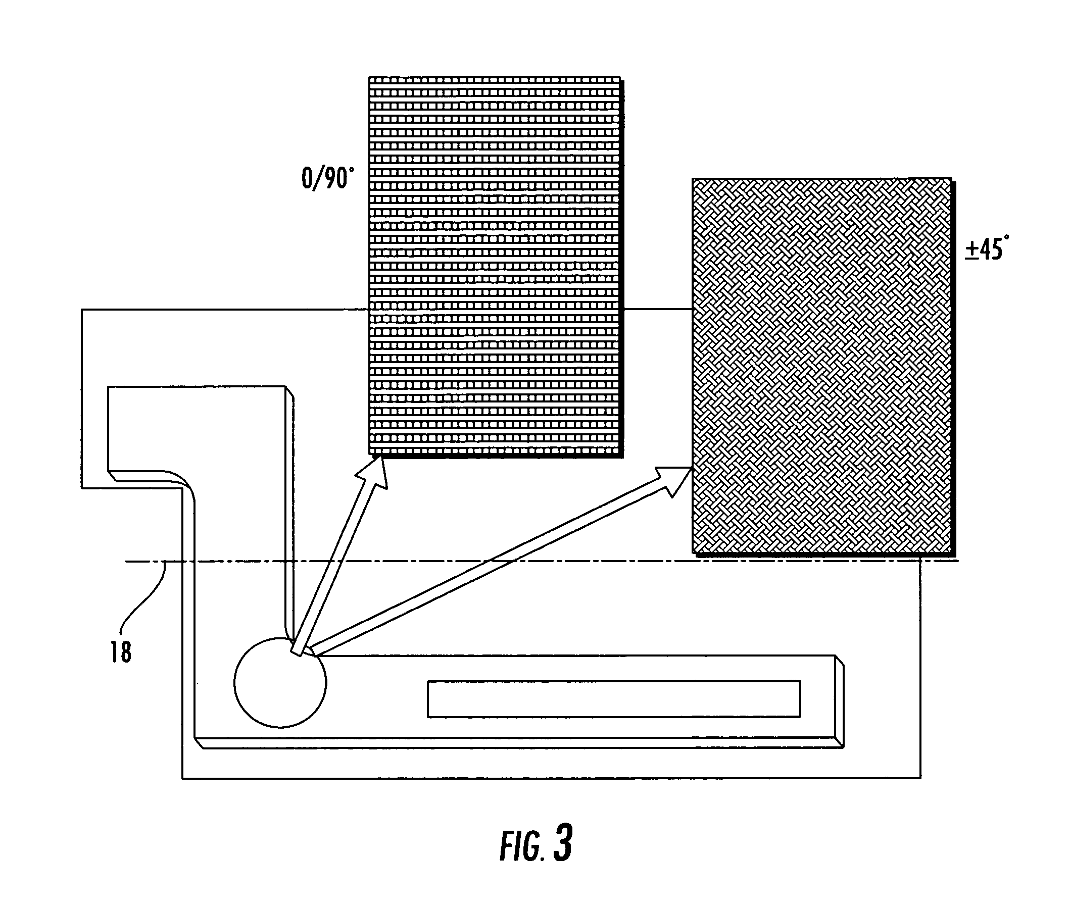
[0014]As shown in FIGS. 1-3, the present invention is directed to a ceramic article 10 that may be used as a replacement for one or more metal components used in a turbine engine. The ceramic article 10 may be formed from CMC oriented unconventionally. In particular, the CMC may be positioned generally orthogonal to a inner sealing surface 22 such that the plane of reinforcing fibers is orthogonal to hot gas path. Such a configuration allows use of hooks and other attachment features where the loading is resisted by the CMC in the strongest direction of the CMC. In addition, the weak interlaminar bonds are oriented generally orthogonal to a inner sealing surface 22, which is the lowest load direction, and are reinforced as described below.

[0015]The ceramic articles 10 may include the use of one or more ceramic plates 12, such as ceramic matrix composite plates. In embodiments having a plurality of ceramic plates 12, the ceramic plates 12 may be positioned together and reinforced usi...


PUM

PropertyMeasurementUnit
temperaturesaaaaaaaaaa
temperatureaaaaaaaaaa
velocityaaaaaaaaaa

Abstract

A ceramic ring segment for a turbine engine that may be used as a replacement for one or more metal components. The ceramic ring segment may be formed from a plurality of ceramic plates, such as ceramic matrix composite plates, that are joined together using a strengthening mechanism to reinforce the ceramic plates while permitting the resulting ceramic article to be used as a replacement for components for turbine systems that are typically metal, thereby taking advantage of the properties provided by ceramic materials. The strengthening mechanism may include a bolt or a plurality of bolts designed to prevent delamination of the ceramic plates when in use by keeping the ceramic plates in compression.

Description

FIELD OF THE INVENTION[0001]This invention is directed generally to ceramic articles, and more particularly to ceramic ring segments that may be used in a turbine system as a replacement for metal components.BACKGROUND OF THE INVENTION[0002]Conventional gas turbine engines operate at high temperatures and therefore, many of the systems within the engine are formed from metals capable of withstanding the high temperature environments. For example, gas turbine systems often include ring segments that are stationary gas turbine components located between stationary vane segments at the tip of a rotating turbine blade or airfoil. Ring segments are exposed to high temperatures and high velocity combustion gases and are typically made from metal. While the metal is capable of withstanding the operating temperatures in earlier engines, the metal is often cooled to enhance the usable life of the ring segments. Many current ring segment designs use a metal ring segment attached either direct...

Claims


Application Information

Patent Timeline
Patent Type & Authority Patents(United States)
IPC IPC(8): F01D11/08
CPCF01D9/04F01D11/08F01D25/246Y10T29/49236F05D2300/21
Inventor GONZALEZ, MALBERTO F.RADONOVICH, DAVID C.SCHIAVO, ANTHONY L.MORRISON, JAY A.VANCE, STEVEN J.
Owner SIEMENS ENERGY INC
Why Eureka
Try Eureka