Method and apparatus for collecting and/or removing sludge

a technology for removing sludge and collecting methods, applied in water cleaning, liquid displacement, separation processes, etc., can solve the problems of heavy machinery and environmental pollution of liquid disposal, and achieve the effect of reducing the number of sludge removal steps

Active Publication Date: 2010-07-13
ULTRA AQUATIC TECH
View PDF18 Cites 12 Cited by
  • Summary
  • Abstract
  • Description
  • Claims
  • Application Information

AI Technical Summary

Benefits of technology

[0015]In another form, the suction head is replaced by a solids screen to prevent large solids being pumped by the pump from the pond. The solids screen may be of the same configuration as the suction head and suitably formed of a mesh-like material.
[0019]Preferably the guide means comprise one or more elongated members. The one or more elongated members may be disposed in an upright attitude such as to indicate the depth of the suction head assembly. The one or more elongated members suitably are connected to the suction head assembly and is / are guided relative to the float members so as to provide a visual indication of the depth of operation of the suction head assembly. Preferably the float members include one or more guides or slide members through which the one or more elongated guide members pass to be captured and guided. Preferably the guide means includes a pair of elongated members, the elongated members being provided at opposite ends of the suction head assembly and extending through opposite guides or slides provided on the float assembly. In a preferred form, the elongated members are pivotally connected to opposite ends of the suction head assembly. Preferably the guide means prevent or substantially limit twisting of the suction head assembly relative to the float assembly. Preferably the guide means guide the suction head assembly for substantially vertical movement beneath the float assembly such that the apparatus has a relatively small footprint.

Problems solved by technology

This creates an environmental problem in liquid disposal.
Further after a pond is drained, heavy machinery is usually required to be used at considerable cost to remove and spread the solid matter which has settled as sludge on the base of the pond.

Method used


Image

  • Method and apparatus for collecting and/or removing sludge
  • Method and apparatus for collecting and/or removing sludge
  • Method and apparatus for collecting and/or removing sludge

Examples


Embodiment Construction

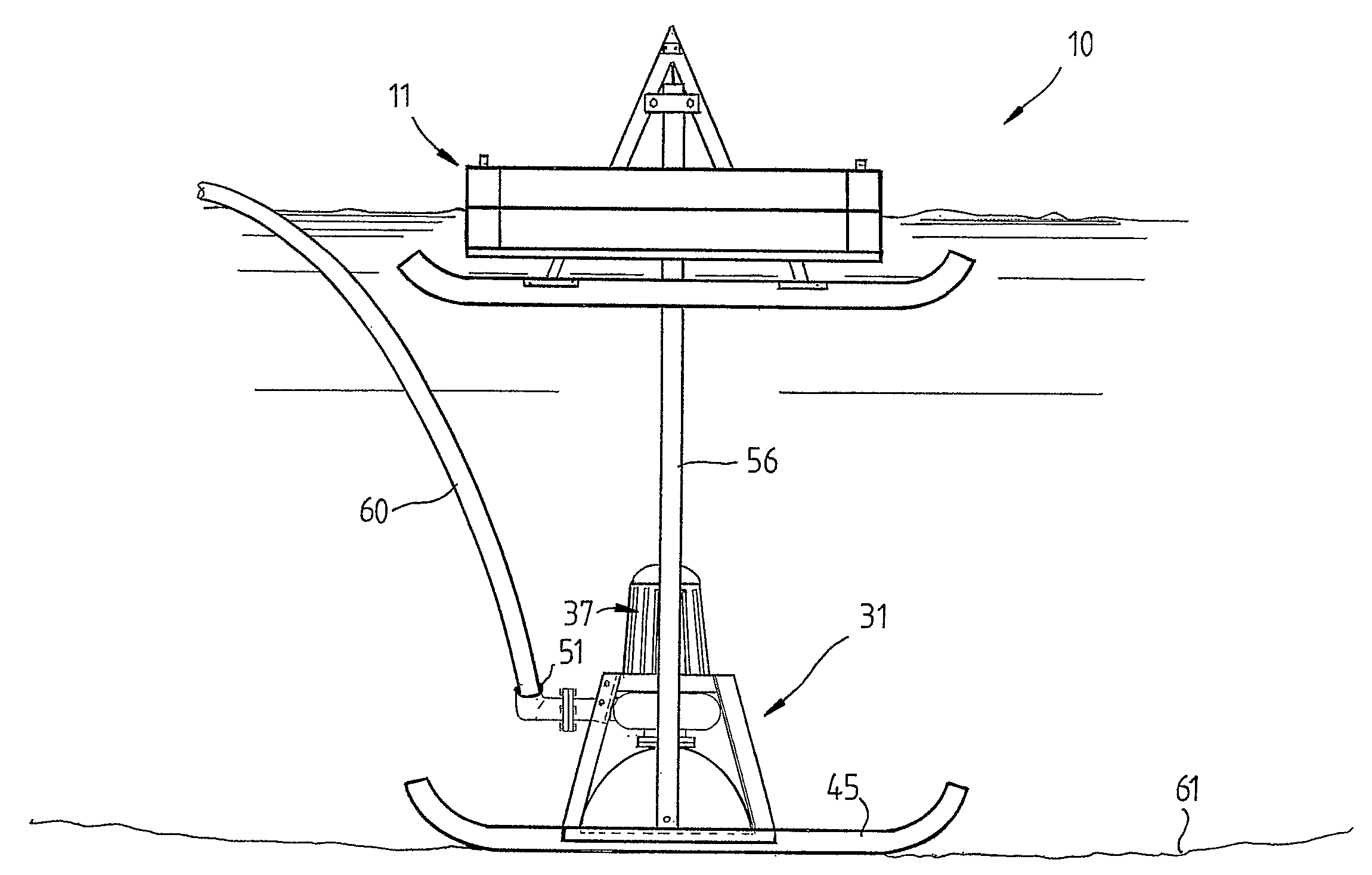
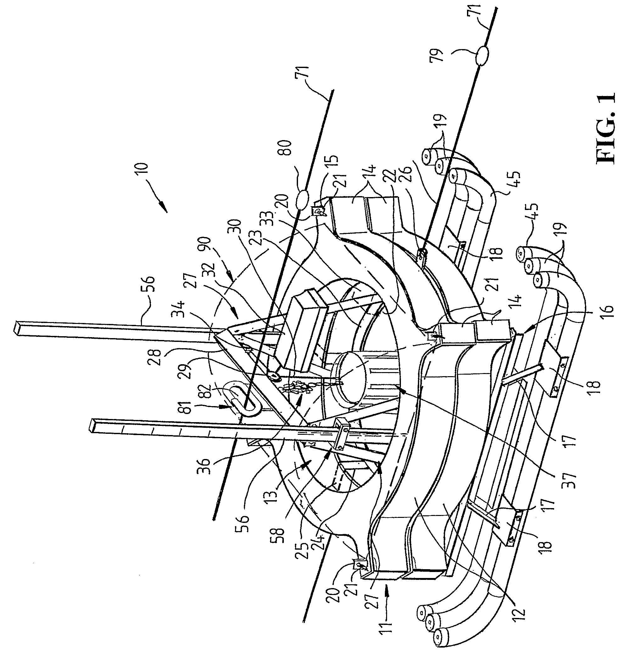
[0032]Referring firstly to FIG. 1, there is illustrated a sludge harvester 10 according to an embodiment of the invention for removing sludge or other material settling on or adjacent the floor of a liquid reservoir such as an effluent pond or other settling pond or for removing materials suspended in liquid in a pond. The sludge harvester 10 includes a float assembly 11 which includes in this embodiment a pair of annular hollow float members 12 having a central hollow interior or opening 13, each float member 12 serving as an air reservoir and for this purpose being sealed to contain air and act as a float. Alternatively, one or more buoyant bodies such as foam plastics members or inserts such as members or inserts of tubular configuration may be located in the hollow float member 12. In an alternative arrangement, a buoyant foam plastics material may be injected into a hollow float member 12. Each hollow float member 12 is provided with circumferentially spaced radially extending ...


PUM

PropertyMeasurementUnit
suction pressureaaaaaaaaaa
depthaaaaaaaaaa
movementaaaaaaaaaa

Abstract

Apparatus for removing solids such as sludge from a liquid reservoir comprising a float, a suction head assembly carrying a pump, and elongated guides interconnecting the suction head assembly and float. The float also carries a winch for raising and lowering the suction head assembly. The guides are slidably engaged with the float and serve to indicate the depth of operation of the suction head assembly.

Description

TECHNICAL FIELD[0001]This invention relates to a method and apparatus for collecting and / or removing sludge or other solids settling or suspended in liquid in a liquid reservoir and in particular but not exclusively to a method an apparatus for collecting and / or removing sludge from shallow ponds such as effluent ponds.BACKGROUND ART[0002]In many situations it is either desirable or necessary to remove sludge and other solids settling in or suspending in liquid in a liquid reservoir. For example, in settling ponds such as settling ponds used in piggeries, dairies, poultry farms and animal feed lots, in sewerage settling ponds, in mining slurry ponds or other ponds, there tends to be an increase in solid matter over a period of time in the pond water. As a result of build up of this solid matter, it is often necessary to empty the pond at regular intervals. This creates an environmental problem in liquid disposal. Further after a pond is drained, heavy machinery is usually required t...

Claims


Application Information

Patent Timeline
Patent Type & Authority Patents(United States)
IPC IPC(8): B01D21/18
CPCB01D21/0027B01D21/04B01D21/2477E02F3/8157E02F3/8841E02F3/8875E02F3/907E02F3/9256E02F3/9293E02F5/28E02F9/065B01D21/2427
Inventor NIELSEN, IAN BRADLEY
Owner ULTRA AQUATIC TECH
Why Eureka
Try Eureka