Plastic component having heat resistant hardened resin at thermal-attachment connection points

a technology of thermal connection and hardening resin, which is applied in the direction of thermoplastic polymer dielectrics, dielectric characteristics, transportation and packaging, etc., can solve the problems of damage to the polymer substance, failure to achieve electrical contact of the soldered element, and impairment of the bonding of the surface metallization, etc., to achieve simple and cost-effective production

Active Publication Date: 2010-07-13
SIEMENS HEALTHCARE GMBH
View PDF9 Cites 4 Cited by
  • Summary
  • Abstract
  • Description
  • Claims
  • Application Information

AI Technical Summary

Benefits of technology

[0009]An object of the present invention is to provide a plastic component that is simple and cost-effective in terms of production and that also enables an unproblematic electrical contacting of additional elements by thermal contacting methods such as soldering.
[0011]The inventive plastic component has a component carrier composed of a commercially available thermoplastic synthetic that is simple to process and cost-effective from the point of view of material costs, on the surface of which however a “heat trap” is attached to protect against unacceptably high thermal load during the soldering of the elements to be contacted. This heat trap is attached in the form of a layer of a duroplastic synthetic or a highly heat-resistant thermoplastic synthetic on which the metal layer serving for the contacting is then applied. The duroplastic synthetic or the highly heat-resistant synthetic is not damaged by the increased temperature upon soldering. The temperature penetration to the substrate material, thus the commercially available thermoplastic synthetic, is slowed; only a slight heating of the substrate material occurs that in no case leads to a damaging. The electrical contacting can be implemented and completed without damaging the substrate material.
[0012]The inventive plastic component consequently allows the use of thermoplastic synthetic that is simple to process and cost-effective with a simultaneous possibility of a secure contacting of additional electrical components since a thermal damage of the base material is advantageously prevented via the applied additional plastic layer (which is preferably applied very thin with a thickness of 5-75 μm, in particular ≦50 μm). The layer serving as a heat protection can thereby be applied over large areas or the entire area on the surface of the component carrier. It is also possible to apply this layer selectively only where a metal layer is required, thus where an element is to be positioned.
[0017]If appropriate, one or more additives (in particular to increase the flammability safety) and / or one or more filler materials can also be added to the duroplastic or highly heat-resistant thermoplastic synthetic layers. The use of some additives or filler materials particular possible without further measures in the cases of the resin systems, since these are made ready for use only immediately before their application.
[0018]For example, TBBA (tetrabrombiphenol A) can be added as an additive to increase the flammability rating. The addition of metallic particles such as palladium, copper or iron is also advantageous because in this case a special primer is no longer necessary for subsequent metallization. For example, glass powder can be used as a filler material to adjust specific physical, chemical or mechanical properties.
[0019]As described, it is sufficient to apply the plastic layer thin with a thickness of 5-75 μm, preferably ≦50 μm. With regard to the very short duration of the thermal load, such layer thicknesses suffice to prevent a too-severe heat transport to the underlying thermoplastic material.

Problems solved by technology

This high temperature load, although brief, normally leads to the polymer substance being damaged.
This local softening generally leads to an impairment of the bonding of the surface metallization, up to the detachment thereof.
This inevitably leads to the situation that the electrical contact of the soldered element also either fails to be accomplished at all, or is accomplished in a sub-standard manner.
In order to prevent a detachment and achieve a good adhesion of the surface metallization with the plastic material, in such cases highly heat-resistant plastics are used, but such plastics require a relatively large effort to produce.
Moreover, such special plastics have high material costs.

Method used


Image

  • Plastic component having heat resistant hardened resin at thermal-attachment connection points
  • Plastic component having heat resistant hardened resin at thermal-attachment connection points

Examples


Embodiment Construction

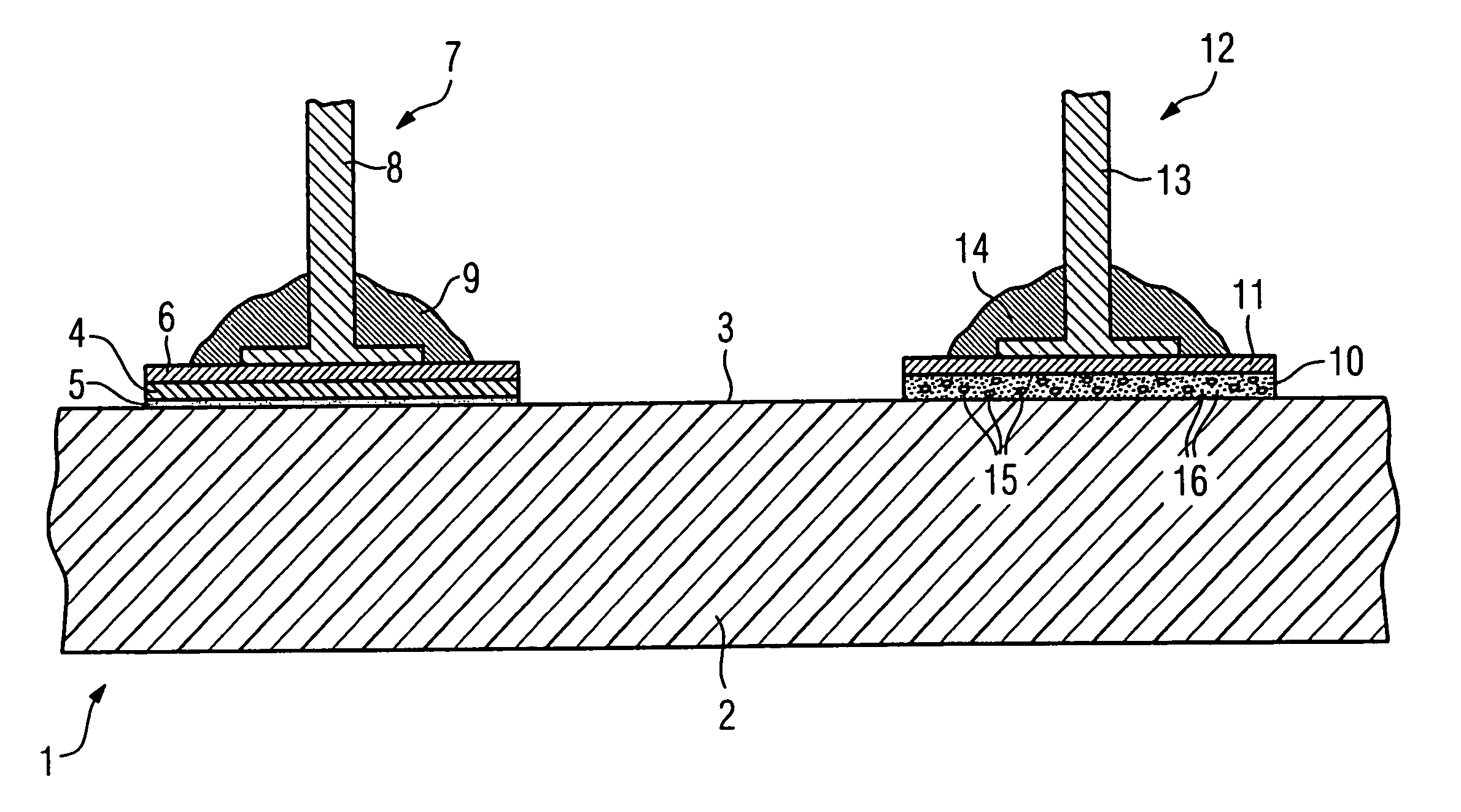
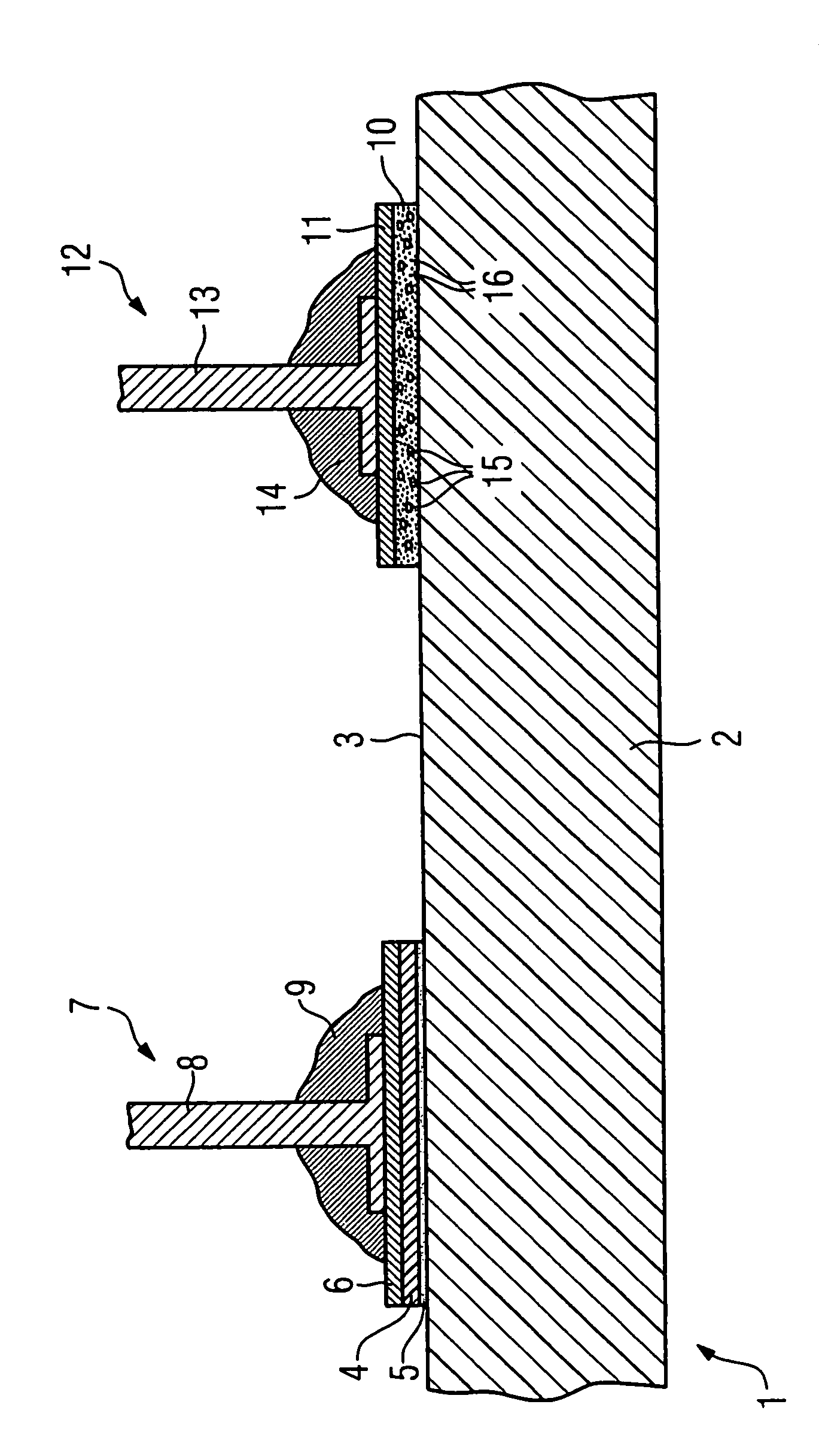
[0022]A sectional view of a portion of an inventive plastic component 1 is shown in the single FIGURE, the plastic component 1 in this example being a housing component of a sheath wave barrier for a magnetic resonance system. The plastic component has a component carrier 2, for example a laminar housing cover plate on its top side 3. The component carrier 2 is composed of a commercially available thermoplastic material of any type.

[0023]In order to be able to contact electrical elements (which are not shown in detail in the FIGURE) with electrical elements located within the housing or the like (likewise not shown in detail), it is sometimes necessary to arrange these on the outside in the region of the surface 3 and to electrically contact these with a surface metallization. This ensues in the course of a soldering method. In order to be able to effect this without thermal damage of the component carrier, a thermal blocking layer in the form of a plastic layer that is resistant to...


PUM

PropertyMeasurementUnit
thicknessaaaaaaaaaa
thicknessaaaaaaaaaa
thicknessaaaaaaaaaa

Abstract

A plastic component with a metal layer applied to the surface for electrical contacting of electrical elements ensuing in a thermal attachment method, particularly in a soldering method, has a layer composed of a duroplastic synthetic or a highly heat-resistant thermoplastic synthetic, on which layer a metal layer is applied, applied on the component carrier made of a thermoplastic synthetic, at least in the region of the contacting point or points. The duroplastic synthetic is a hardened resin, and the resin layer is generated by application of the liquid resin by serigraphy, roller coating or spraying, or the highly heat-resistant thermoplastic synthetic is applied in the form of a film.

Description

BACKGROUND OF THE INVENTION[0001]1. Field of the Invention[0002]The present invention concerns a plastic (synthetic) component of the type having a metal layer applied to the surface for electrical contacting of electrical elements by a thermal attachment method, particularly a soldering method, having a layer of a duroplastic synthetic, a highly heat-resistant thermoplastic synthetic, on which the metal layer is applied, applied on the component carrier that is also made of a thermoplastic synthetic, at least in the region of the contacting point or points.[0003]2. Description of the Prior Art[0004]In different applications it is sometimes necessary to attach one or more further electrical elements on a plastic component provided with a metal layer applied on its surface and, via the metal layer, to contact further elements therewith. This electrical contacting normally ensues in a soldering method, meaning that the components to be connected with the metal layer are thermally sold...

Claims


Application Information

Patent Timeline
Patent Type & Authority Patents(United States)
IPC IPC(8): H05K1/00C08J7/046
CPCB29C65/5021B29C66/1142B29C66/43B29C66/4722B29C66/742B32B15/08C08J7/045C09D5/38H05K1/0201H05K3/386B29C65/5057B29C65/00Y10T428/264B29C66/43441B29K2071/00B29K2079/085B29K2081/04B29K2081/06B29K2101/10B29K2101/12B29K2105/0079B29K2995/0015B29K2995/0039B29K2995/004H05K1/0313H05K1/111H05K3/3421H05K2201/0129H05K2201/10318B29C65/483B29C65/481B29C65/4865B29C66/1122B29C66/73921B29C66/71Y10T428/31681Y10T428/31678C08J7/0423C08J7/046
Inventor GLOEDE, STEFANHAGEN, JURGEN
Owner SIEMENS HEALTHCARE GMBH
Why Eureka
Try Eureka