Filler tube assembly

a technology of tube assembly and tube body, which is applied in the direction of load accommodation, liquid handling, packaging goods type, etc., can solve the problems of fuel contamination of lakes, rivers, other waterways, and the resulting pollution of waterways, and the penalties for violating such laws are severe, and the effect of overflow

Active Publication Date: 2010-07-20
SMITH DAVID G
View PDF32 Cites 12 Cited by
  • Summary
  • Abstract
  • Description
  • Claims
  • Application Information

AI Technical Summary

Benefits of technology

[0013]Accordingly, the operator of the fuel pump nozzle may seat the fuel pump nozzle against the rim to assure that the pressure sensing port is aligned with the orifice. Because the vacuum tube provides fluid communication between the fuel tank and the orifice, a pressure change at the open end of the vacuum tube is transmitted to the orifice. Further, the pressure difference at the orifice is sensed by the fuel pump nozzle through the pressure sensing port. As such, when the open end of the vacuum tube is covered, e.g., with fuel, a pressure change at the open end is transmitted through the vacuum tube to the orifice and to the pressure sensing port of the fuel pump nozzle. The open end of the vacuum tube may be located at a predetermined level to prevent leakage of fuel through the vent tube and / or to leave excess volume to accommodate for thermal expansion of fuel.

Problems solved by technology

Fuel overflow during the fueling of boats is common and results in fuel contamination of lakes, rivers, and other waterways.
Federal law prohibits spilling fuel into a lake, river, or waterway, and penalties for violating such laws may be severe.
Such fuel overflow has been reduced by advancements in fuel pump nozzles, but such advancements have not eliminated overflow and the resulting pollution of waterways.
Belching may also be caused by air that is trapped with the fuel as the fuel enters the fuel fill neck.
As a result the backpressure created by the air restricts or eliminates fuel flow, generally at which point the fill neck belches, or releases, the air through the receiver fitting, which may result in fuel splashing out of the receiver fitting.

Method used


Image

  • Filler tube assembly
  • Filler tube assembly
  • Filler tube assembly

Examples


Embodiment Construction

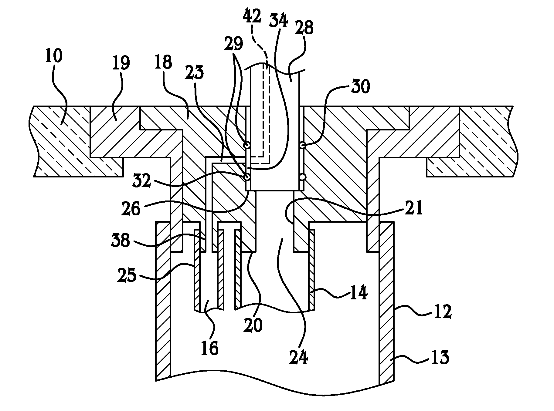
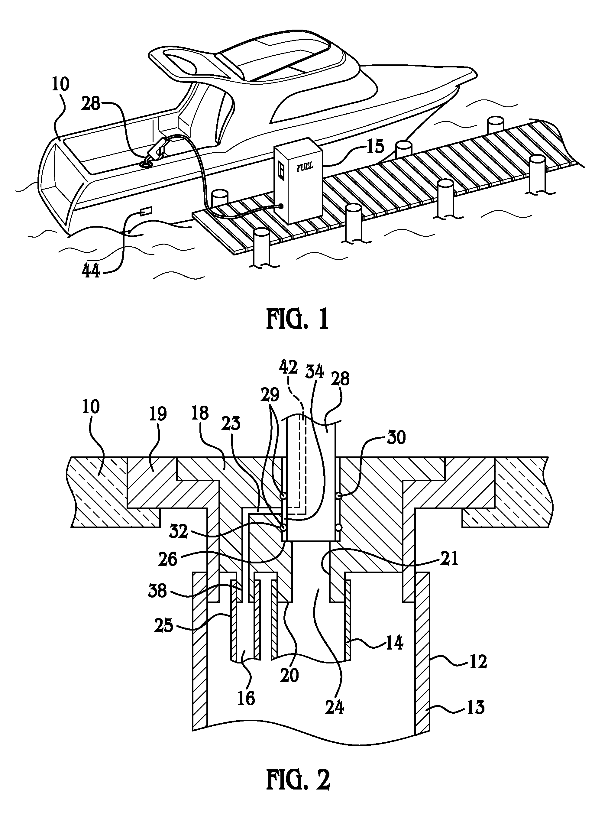
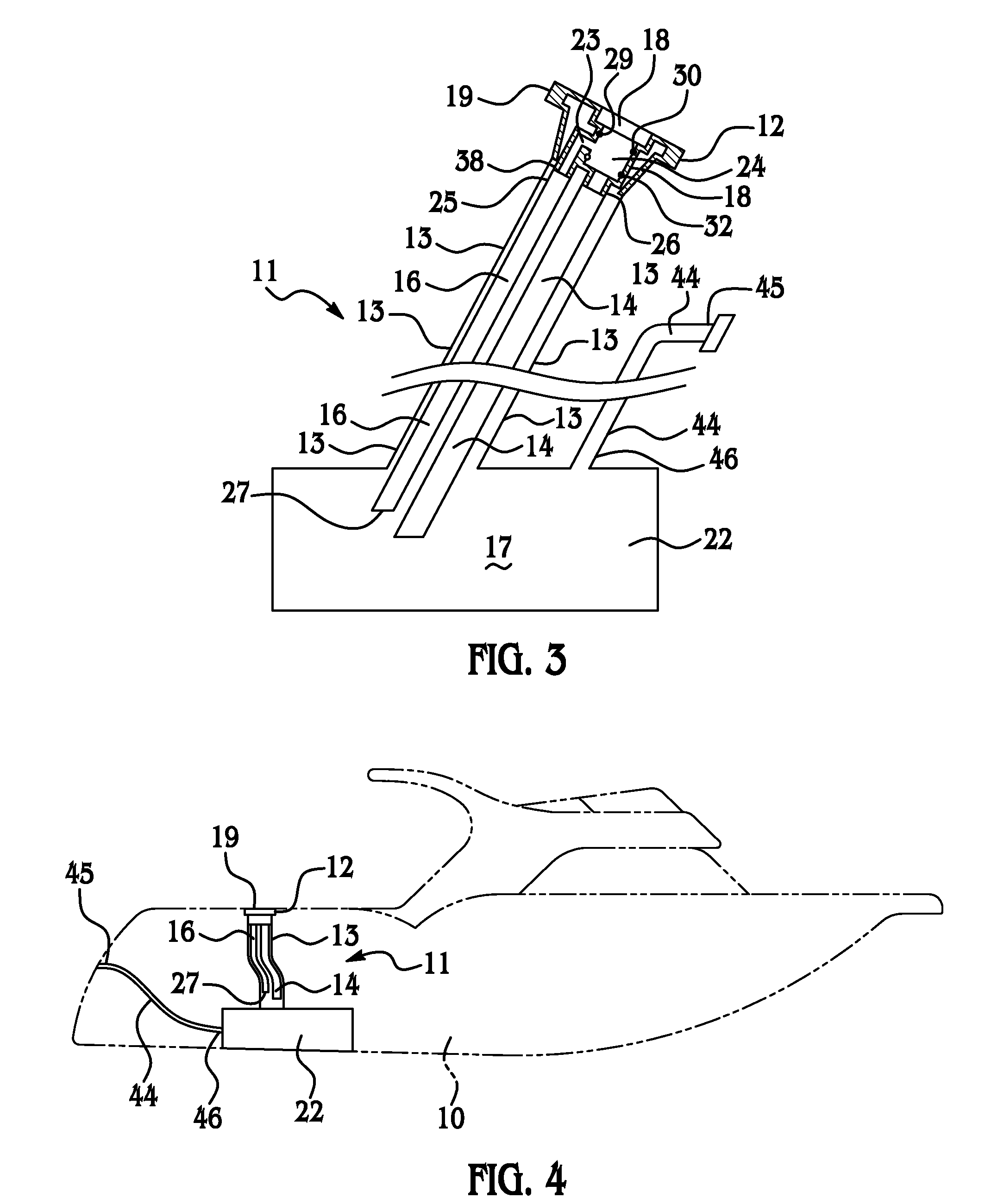
[0026]Referring to the Figures, wherein like numerals indicate like or corresponding parts throughout the several views, a fuel storage system 11 is generally shown. The fuel storage system 11 receives fuel from a fuel pump nozzle 28 having a pressure sensing port 42. For example, the fuel pump nozzle 28 may be found in a standard fuel filling station and may be coupled to a fuel pump 15. As is known in the art, the fuel pump nozzle 28 includes an automatic shut-off system. When activated, the automatic shut-off system discontinues the flow of fuel through the fuel pump nozzle 28. Specifically, the automatic shut-off system responds to a pressure change at the pressure sensing port 42. The fuel pump nozzle 28 draws a vacuum through the pressure sensing port 42 and when the pressure sensing port 42 is covered, e.g., with fuel, the automatic shut-off system senses the change in pressure and discontinues the flow of fuel through the fuel pump nozzle 28.

[0027]The fuel storage system 11 ...


PUM

PropertyMeasurementUnit
pressureaaaaaaaaaa
inner diameteraaaaaaaaaa
resilientaaaaaaaaaa

Abstract

A filler tube assembly is used with a fuel pump nozzle having a pressure sensing port. The filler tube assembly includes a receiver having an inner wall defining an aperture, which receives the pump nozzle. The inner wall defines an orifice and a seal is coupled to the inner wall about the orifice for defining a chamber between the inner wall, the seal, and the fuel pump nozzle when the fuel pump nozzle is disposed in the aperture. A vacuum tube has a coupled end in fluid communication with the orifice and an open end in fluid communication with the fuel tank. The receiver defines a rim for seating the fuel pump nozzle in the aperture to align the pressure sensing port with the orifice. When fuel covers the open end of the vacuum tube, a pressure change is transmitted through the filler tube assembly to the pressure sensing port.

Description

CROSS REFERENCE TO RELATED APPLICATION[0001]This application claims the benefit of Provisional Application Ser. No. 60 / 754,873 filed Dec. 29, 2005, which is incorporated herein by reference.BACKGROUND OF THE INVENTION[0002]1. Field of the Invention[0003]The present invention is a filler tube assembly for communicating fuel from a fuel pump nozzle to a fuel tank with the fuel pump nozzle having a pressure sensing port.[0004]2. Description of the Related Art[0005]Fuel overflow during the fueling of boats is common and results in fuel contamination of lakes, rivers, and other waterways. Federal law prohibits spilling fuel into a lake, river, or waterway, and penalties for violating such laws may be severe. Such fuel overflow has been reduced by advancements in fuel pump nozzles, but such advancements have not eliminated overflow and the resulting pollution of waterways.[0006]Boats generally include a fuel tank and a filler tube assembly extending from a surface of the boat to the fuel ...

Claims


Application Information

Patent Timeline
Patent Type & Authority Patents(United States)
IPC IPC(8): B65B1/30
CPCB63B25/082
Inventor SMITH, GREGORY F.SMITH, DAVID G.
Owner SMITH DAVID G
Why Eureka
Try Eureka