Gravity wave power generation apparatus

a technology of gravity wave and power generation apparatus, which is applied in the direction of electric generator control, couplings, fluid couplings, etc., can solve the problems of ocean water temperature fluctuations, and achieve the effects of high flexibility and economical efficiency, efficient capture of wind power energy and gravitational energy above the ocean, and large amount of generated electric power

Inactive Publication Date: 2010-07-20
FUJISATO TETABUHIKO +1
View PDF15 Cites 41 Cited by
  • Summary
  • Abstract
  • Description
  • Claims
  • Application Information

AI Technical Summary

Benefits of technology

[0016]The gravity wave power generation apparatus based on the second embodiment of the present invention is comprised of a filling and draining valve for drawing in or draining out the ocean water inside the floating body, a reel for reeling in and out the wire rope on the mooring member, and a compressor for draining out the ocean water inside the floating body using the compressed air to increase the buoyancy of the entire apparatus, in order to protect the entire apparatus from the impact of strong waves by adjusting to the weather conditions such as typhoons and precipitating the apparatus into the ocean.
[0042](b) Further, when the fourth embodiment is operated in combination with the third embodiment, the seesaw motion of the weight mass as well as the amount of generated electric power are further increased, thus, resulting in a high economical efficiency.

Problems solved by technology

The distribution of solar heat energy, which is the largest energy covering the surface of the earth, is not uniform, and creates an imbalance even in the ocean waters that largely absorbs from the surface of the earth, thus, creating an imbalance in the ocean water temperature as well.

Method used


Image

  • Gravity wave power generation apparatus
  • Gravity wave power generation apparatus
  • Gravity wave power generation apparatus

Examples


Embodiment Construction

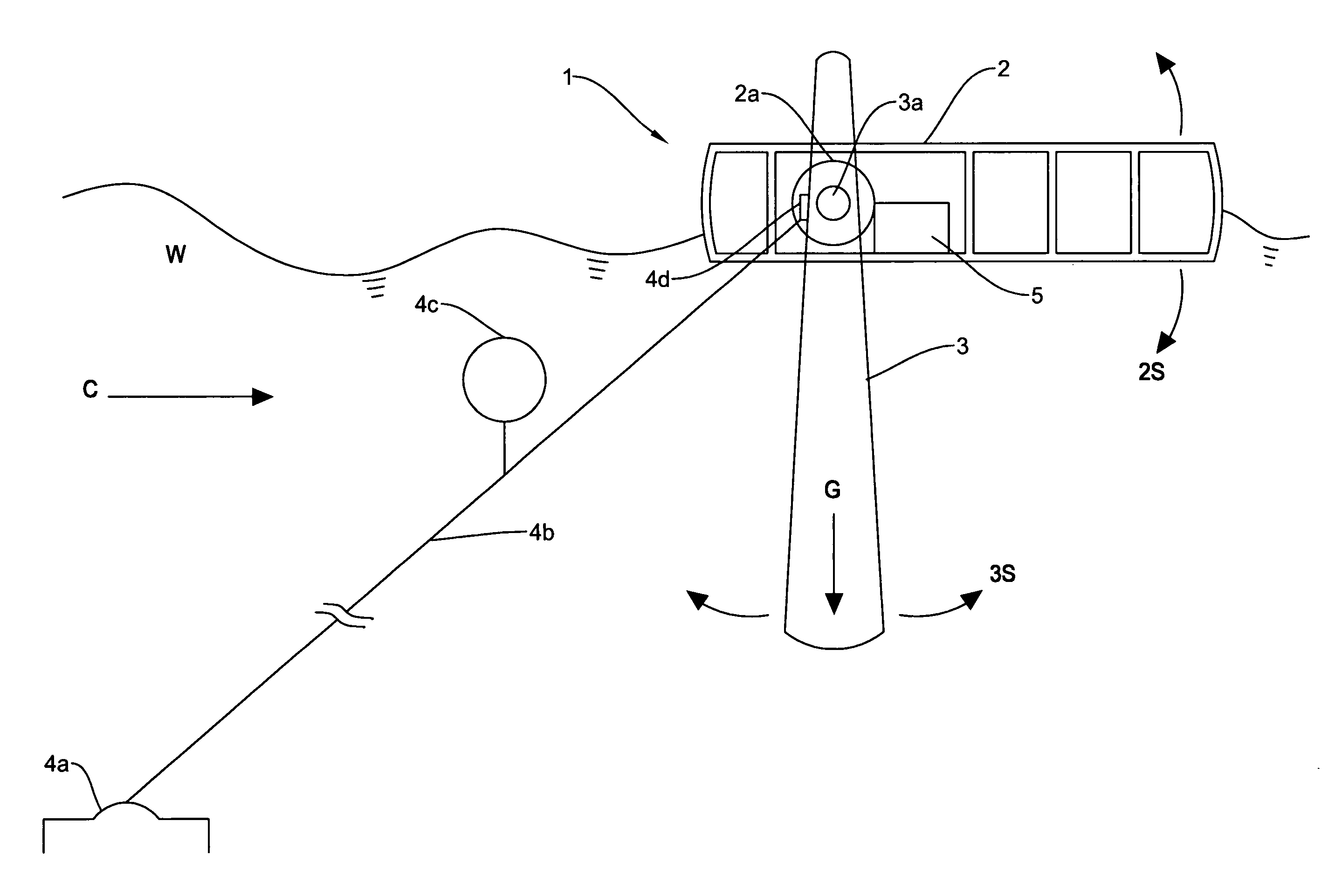
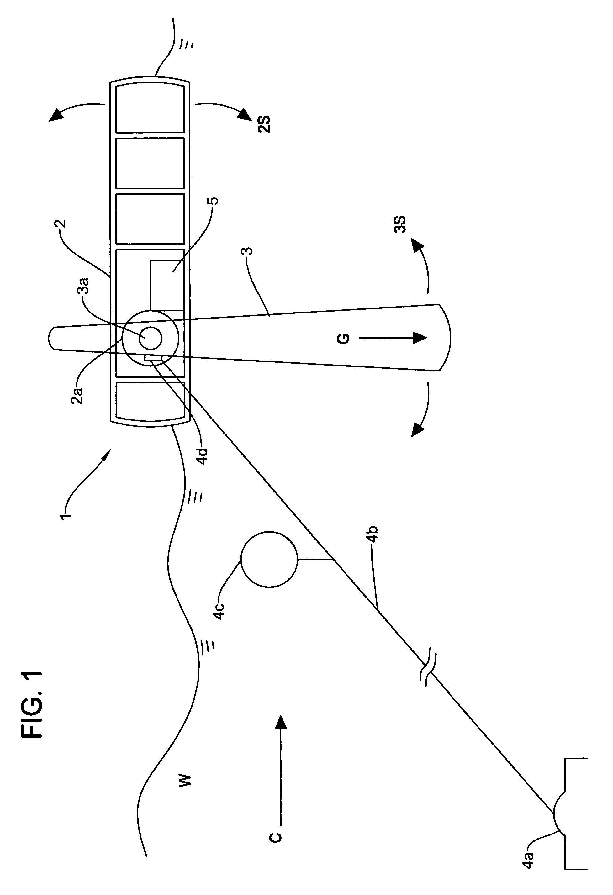
[0077]FIG. 1 is a schematic diagram showing a structure of the embodiment of the gravity wave power generation apparatus 1 in the present invention, where W denotes waves, C denotes stream current such as ocean current and tidal current, and G denotes gravity.

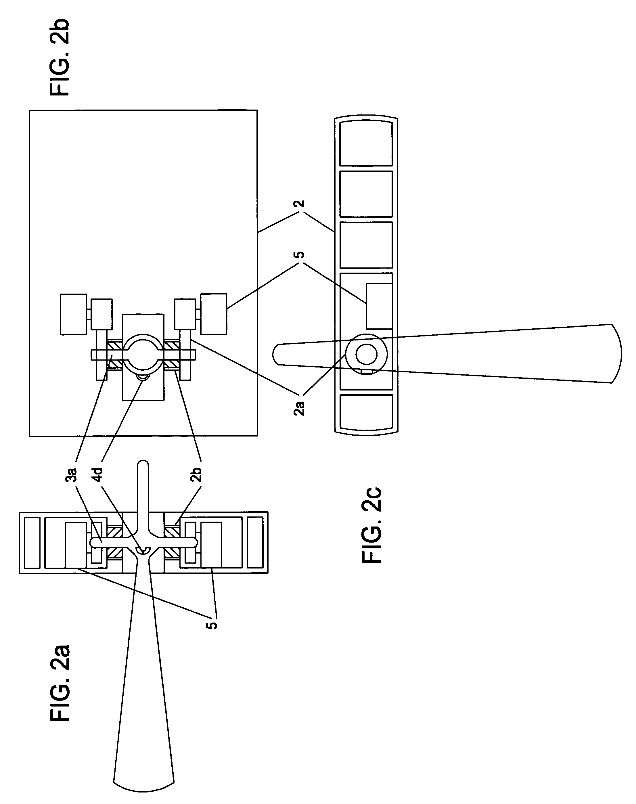
[0078]Reference numeral 1 denotes the gravity wave power generation apparatus, reference 2 denotes a floating body that is floating on the ocean surface, reference 2S denotes an up and down motion of the floating body that is moving in response to the waves, reference 2a denotes a normal rotation converter where the reverse motion of rotation axis 3a going through a bearing 2b created by the up and down motion of floating body 2 is converted into a normal rotation by a one-way clutch or a ratchet mechanism, reference 2b denotes a bearing where the left and right side thereof is stabilized and attached to floating body 2, reference 3 denotes a weight mass pulled towards the bottom of the ocean by the gravity G, reference 3a deno...


PUM


Abstract

A power generation apparatus that will not exhaust carbon dioxide is provided where a strong rotating motion is created by the combination of solar heat energy, gravitational energy, and ocean current or tidal current energy. In the sea area having stream current such as ocean current and tidal current, the power generation apparatus is constructed by a weight mass provided with a rotation axis (shaft) on the top part thereof, a floating body provided with a bearing for fitting in the rotation axis where it moves up and down according to the swell on the ocean surface, a normal rotation conversion generator for converting the reverse motion produced on the rotation axis to a normal rotating motion by using a one-way clutch or a ratchet mechanism, and a mooring member for fastening the wire rope between the anchor and the connecting point of the floating body and weight mass.

Description

FIELD OF THE INVENTION[0001]The present invention relates to a gravity wave power generation apparatus incorporated in the sea area having stream current such as ocean current and tidal current that is capable of producing natural energy made up of wave power energy, gravitational energy, and current energy by establishing a bearing on the buoyant body that is catching the waves (swell) from the sea area, fitting a weight mass attached to a rotation axis (shaft) on that buoyant body, and mooring it to an anchor established at the bottom of the sea, where a reverse motion of the rotation axis is converted into a normal rotating motion by using a one-way clutch or a ratchet mechanism.BACKGROUND OF THE INVENTION[0002]A natural energy generation apparatus that combines waves, gravity, and current does not exist, thus, an ocean current generation and a wave power generation will be used as a reference. As for other natural energy generation apparatuses, there are ones using solar heat, w...

Claims


Application Information

Patent Timeline
Patent Type & Authority Patents(United States)
IPC IPC(8): H02P13/00F03G3/06
CPCF03B13/1815Y02E10/38Y02E10/30
Inventor FUJISATO, TETSUHIKO
Owner FUJISATO TETABUHIKO
Why Eureka
Try Eureka