Electronic lamp identification system

a technology of electronic lamps and identification systems, applied in the field of identification systems, can solve the problems of insufficient disinfection, negative effect of system operation for general illumination or special lighting purposes, and sunburn of users' skin, so as to prevent physical injury, prevent insufficient disinfection, and simple magnetic coupling.

Active Publication Date: 2010-07-20
SIGNIFY HLDG BV
View PDF19 Cites 12 Cited by
  • Summary
  • Abstract
  • Description
  • Claims
  • Application Information

AI Technical Summary

Benefits of technology

[0011]An embodiment of the identification system according to the invention is characterized in that the identification system is further arranged for controlling the operation of the light radiation source in dependence on data retrieved from the identification circuit. Only if the result of the identification is positive, the lamp is switched on, thus preventing an improper operation of a lighting device, for example after incorrect lamp replacement.
[0026]An embodiment of the light radiation source according to the invention is characterized in that the light radiation source is a mercury vapor discharge lamp for generating UV radiation for suntanning purposes or for disinfection purposes. Identification of these lamps can prevent physical injury caused by the use of an incorrect type of lamp and can prevent an insufficient degree of disinfection.

Problems solved by technology

In case of replacement of a lamp that has become unusable, the operation of a system for general illumination or for special lighting purposes is negatively affected if a lamp with either too high or too low a radiation intensity is installed.
When the lamps of a solarium are replaced, installing lamps with a too high UV radiation output would cause sunburn of the user's skin.
UV lamps used for disinfection purposes with a too low UV radiation output will result in an insufficient degree of disinfection.
When using UV or infrared lamps, for example for medical purposes, a too low or too high luminous intensity of the lamps after incorrect lamp replacement may result in an improper treatment of the patient.
An incorrect replacement of lamps for general illumination purposes may result in an insufficient level of illumination on the one hand or a too high power consumption and possibly damage to the lampholder on the other hand.
It is a disadvantage of the prior art identification system that a proper functioning of the identification system is prohibited if the impedance of the lamp electrode is relatively low, for example with high signal frequencies in the range of 3-30 MHz, since the identification element cannot be interrogated reliably any more.

Method used


Image

  • Electronic lamp identification system
  • Electronic lamp identification system
  • Electronic lamp identification system

Examples


Embodiment Construction

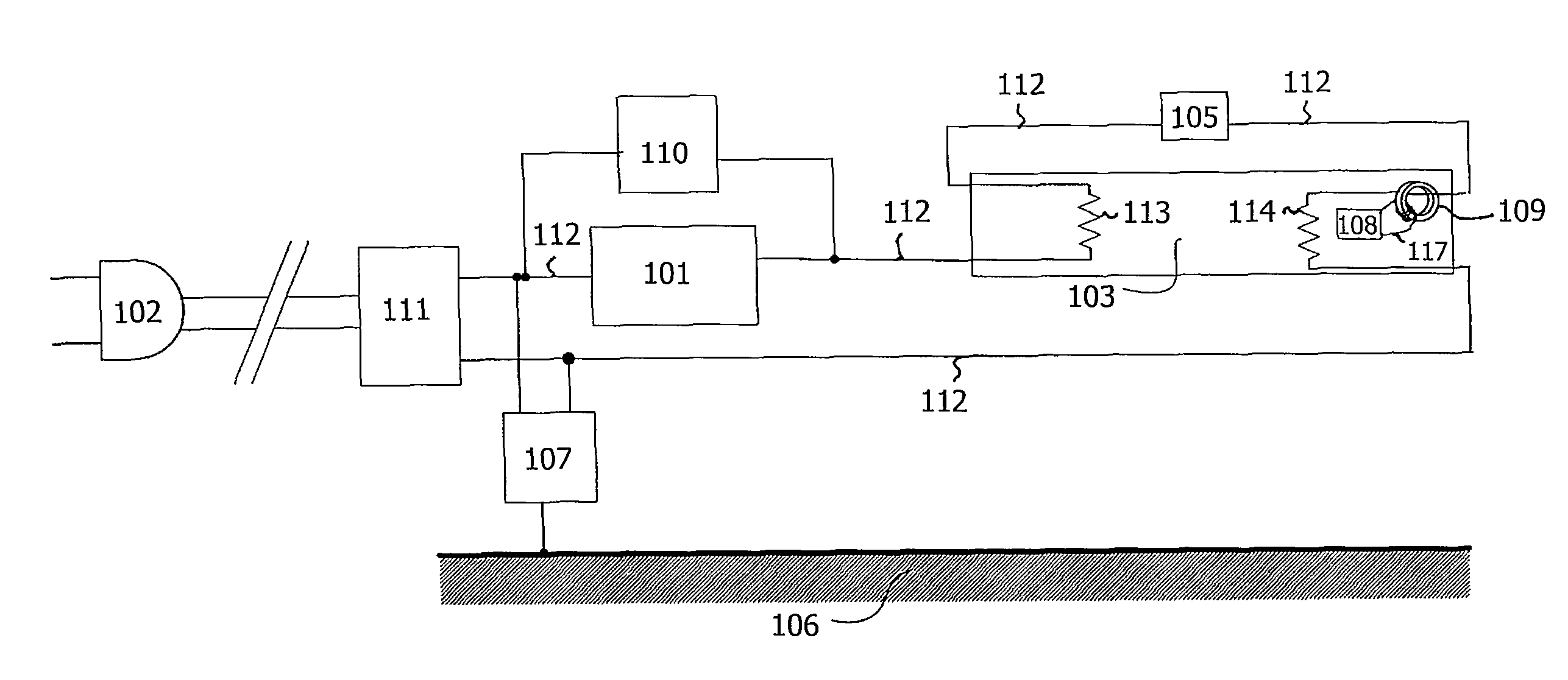
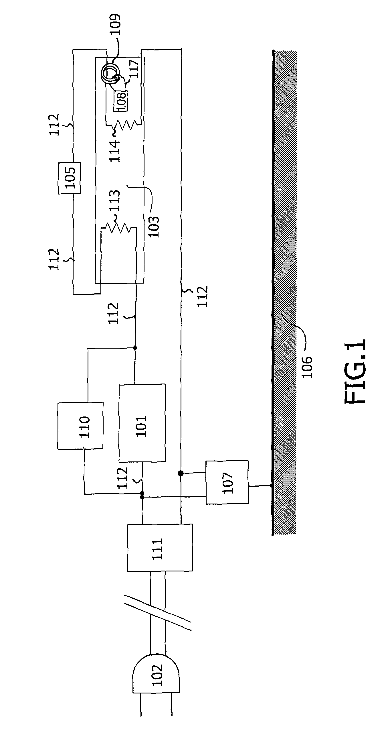
[0036]FIG. 1 schematically shows a mercury vapor discharge lamp 103 having an identification circuit 108, and an identification system having a controller 107. The lamp 103 is connected to the power grid via connector 102, and the lamp is powered via ballast circuit 101. The ballast circuit 101 may be an electronic ballast or an electromagnetic ballast. The ballast circuit 101 is coupled in series with the electric wire 112 in one direction. The lamp 103 is, for example, a UV radiation source in a solarium, a disinfection installation lamp, or a device for medical treatment, or alternatively a visible light radiation source for general illumination purposes, or for liquid crystal display backlighting applications. In an alternative embodiment, the controller 107 is integrated into the ballast circuit 101. The ballast circuit 101 and the controller 107 are connected to the lamp 103 via an electric wire 112. The electric wire may comprise sockets, not shown in FIG. 1, as well as elect...


PUM


Abstract

An identification system for a light radiation source (103) having a control circuit (107) for communicating with an identification circuit (108) associated with the light radiation source, wherein the identification circuit is arranged for storing data relating to the light radiation source. During operation, the control circuit communicates with the identification circuit via a signal path comprising at least a portion of a first electric wire (112) provided for energizing the light radiation source such that it is used as a first transmitting antenna for communicating with the identification circuit. The operation of the light radiation source is controlled in dependence on the data retrieved from the identification circuit. Depending on the result of the identification, operation of the light radiation source can be authorized or prevented, thus blocking the use of an incorrect radiation source for a given application.

Description

TECHNICAL FIELD[0001]The invention relates to an identification system for a light radiation source, comprising a control circuit for communicating with an identification circuit associated with the light radiation source, wherein the identification circuit is arranged for storing data relating to the light radiation source, and wherein, during operation, the control circuit communicates with the identification circuit via a signal path comprising at least a portion of a first electric wire provided for energizing the light radiation source.[0002]The invention further relates to a method of operating a light radiation source, in which said identification system is used.[0003]The invention further relates to a light radiation source suitable for cooperating with said identification system.[0004]The invention further relates to a solarium comprising said identification system.[0005]The invention further relates to a UV disinfection system comprising said identification system.BACKGROU...

Claims


Application Information

Patent Timeline
Patent Type & Authority Patents(United States)
IPC IPC(8): G01J1/00
CPCA61N5/0614A61N2005/0661H05B41/36H05B47/20
Inventor MASTENBROEK, OLAFLULOFS, KLAAS JACOB
Owner SIGNIFY HLDG BV
Why Eureka
Try Eureka