Dual-rotary-coupling, internal-waveguide linac for IORT

a linac and iort technology, applied in the field of mobile electromedical equipment, can solve the problems of limiting the freedom of pitch angular range of the radiating head, affecting the safety of persons, and subject to a wear ra

Inactive Publication Date: 2010-07-20
GATTO POMPILIO
View PDF2 Cites 6 Cited by
  • Summary
  • Abstract
  • Description
  • Claims
  • Application Information

AI Technical Summary

Benefits of technology

[0013]Therefore, it is the object of this invention to provide an internal-waveguide linac for IORT wherein the aforesaid flexible waveguide and the restrictions connected thereto are removed; particularly, wherein the radiating head has a pitch angular range of ±90°; and wherein the pitch angle of the radiating head turns out to be precisely measured, so that the angular position thereof, as results also from the roll and pitch rotations thereof, and, consequently, the direction in space of the electron beam at the output of the linac assembled in the head turn out to be precisely computable.

Problems solved by technology

Indeed, it is subject to a wear rate, and it determines a limit to the freedom of pitch angular range of the radiating head within ±45°.
Indeed, this radiation is dangerous for the persons who are in or pass through the places below the operating room.
On the contrary, the deformations the flexible guide undergoes in its operation do not allow a precise measurement of the pitch angular position of the radiating head.

Method used


Image

  • Dual-rotary-coupling, internal-waveguide linac for IORT
  • Dual-rotary-coupling, internal-waveguide linac for IORT

Examples


Embodiment Construction

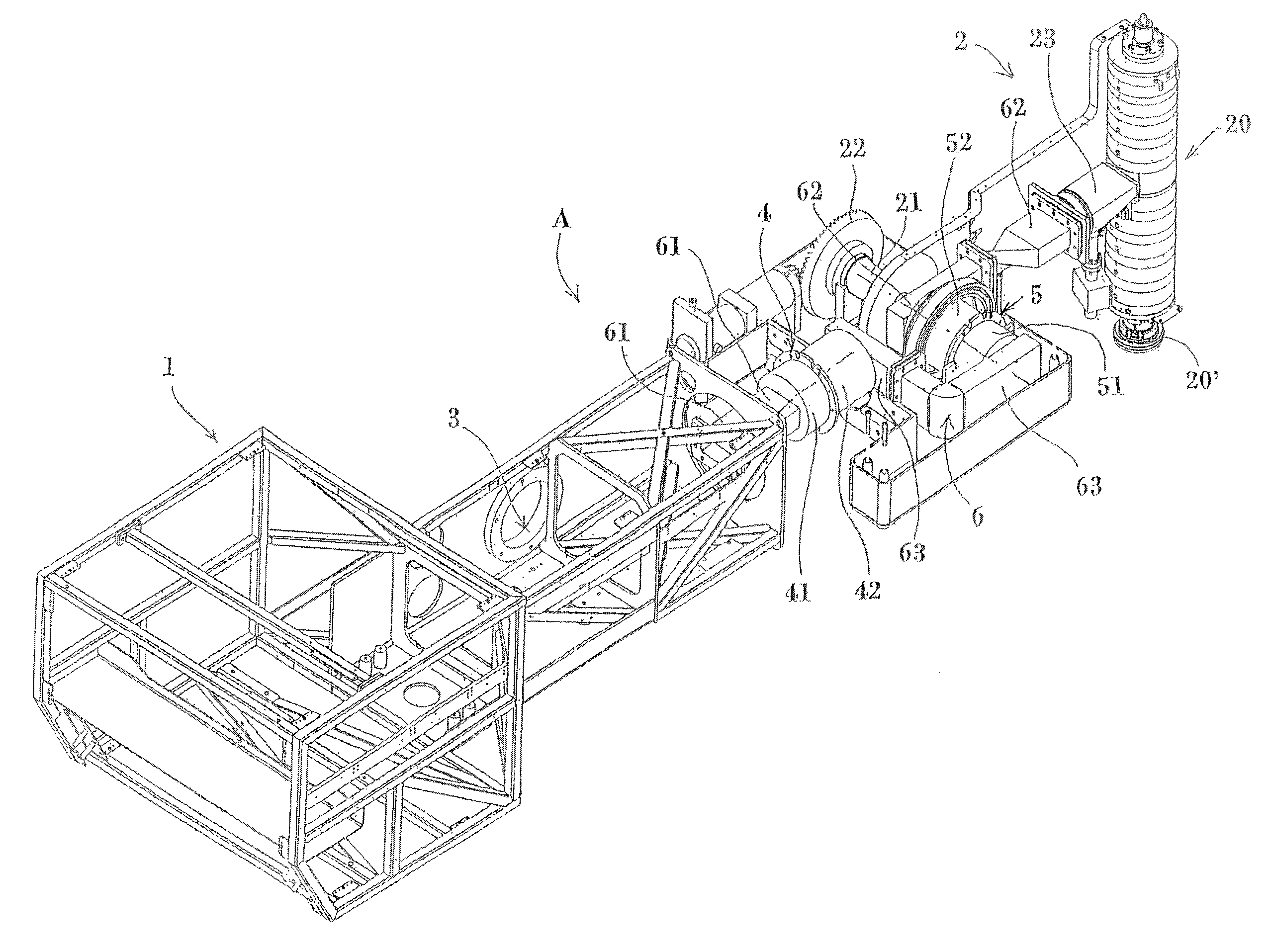
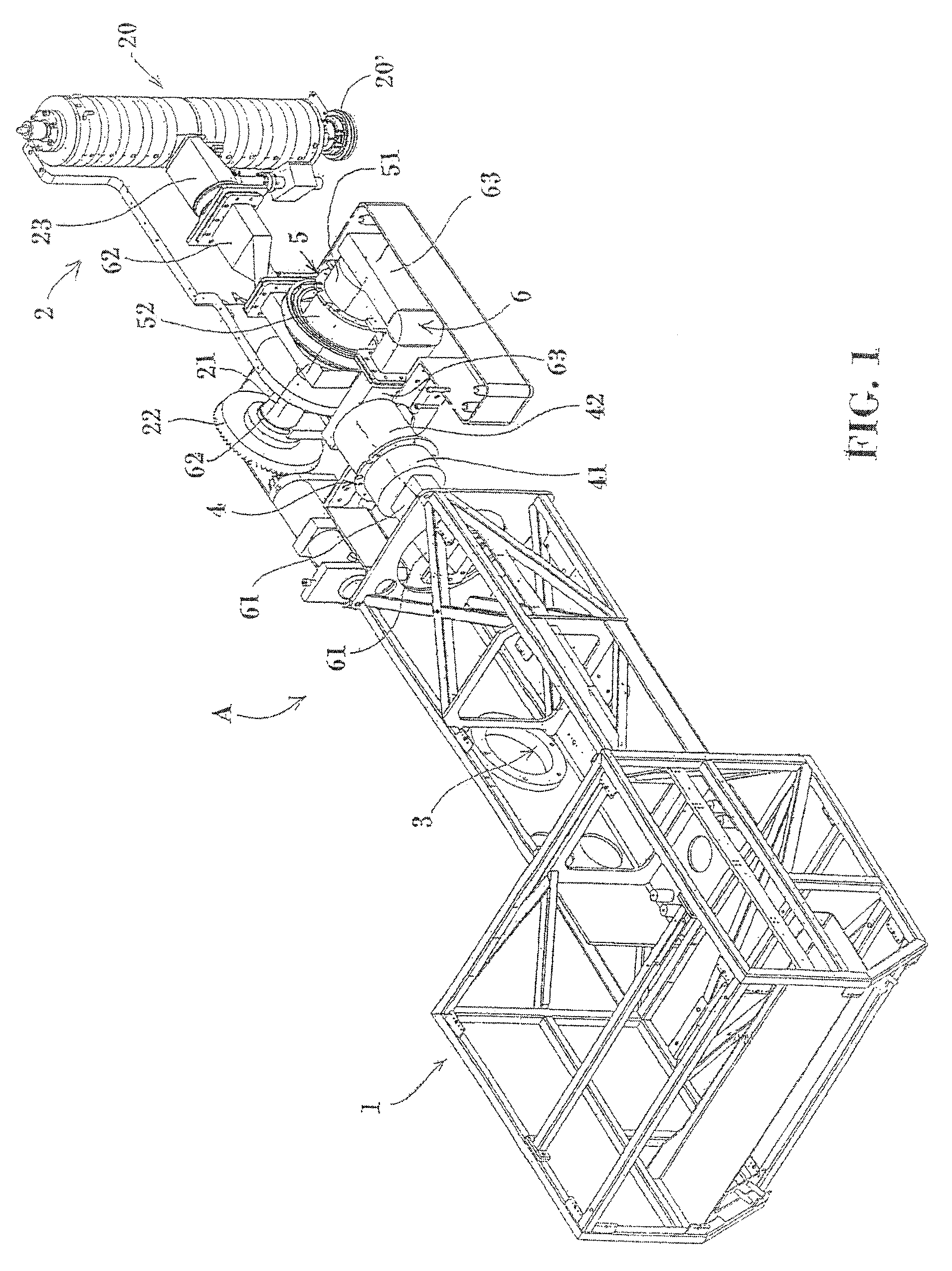
[0020]Articulated arm A is represented in FIG. 1 of a linac apparatus for IORT, comprising at a first extremity thereof a housing 1 intended to contain a high-voltage power-supply and a RF generator assembly including an oscillator, e.g. a cavity magnetron or a klystron. At a second extremity, opposite the first one, arm A supports a radiating head 2 including an electron linac 20, endowed with an output diaphragm 20′ of the electron beam emitted by the linac.

[0021]Arm A is assembled through an arm coupling 3 which supports it in pitch motion, on a link (not represented) built for being assembled in yaw motion on a motor mobile bedplate (not represented). The coupling of arm 3 finds itself in an intermediate position between housing 1 and radiating head 2.

[0022]Radiating head 2 is mechanically assembled onto articulated arm A by means of the combination of a first and of a second rotary coupling. First rotary coupling, or roll coupling 4 includes a fixed portion 41, integral with ar...


PUM


Abstract

Electromedical apparatus for intraoperative radiotherapy via a linac. It includes an arm in which, at an extremity thereof, an oscillator is assembled which generates electromagnetic waves, and which supports, at an opposite extremity thereof, a radiating head in which a linac is assembled, emitting at its output an electron beam, supplied by the oscillator through a guiding structure. The apparatus includes a first and a second rotary couplings, respectively including a fixed portion and a mobile portion, endowed with sensors of the angular position of the mobile portions, which support the radiating head on the arm in roll and pitch motion. The guiding structure includes three separate rigid waveguides, of which one at the output of the oscillator and one of input to the linac, and an intermediate one therebetween, which connects them, with the heads of which they are respectively connected through the first and the second rotary couplings.

Description

DISCLOSURE OF THE INVENTION[0001]1. Technical Field[0002]The present invention relates to a mobile electromedical apparatus for Intraoperative RadioTherapy (or “IORT”) by means of an electron Linear Accelerator (or “linac”).[0003]2. Background Art[0004]An electron linac is an evacuated waveguide in which a high-frequency traveling electromagnetic wave is excited, the axial electric field of which accelerates electrons. The phase velocity of the wave is made equal to the velocity of electrons by assembling irises in the guide, which delimitate accelerating coupled resonant cavities. The linac is supplied by a radiofrequency (or “RF”) oscillator, particularly a cavity magnetron, through a guiding structure or means (any structure or means being meant, by such an expression, fit for guiding electromagnetic waves, e.g. rectangular or circular waveguides, and coaxial cables). A feature of a linac is the collimation of the beam, i.e. the parallelism of the trajectories of the electrons it...

Claims


Application Information

Patent Timeline
Patent Type & Authority Patents(United States)
IPC IPC(8): H05H9/00H01J35/10
CPCA61N5/10A61N5/1081A61N5/01A61N2005/1089
Inventor GATTO, POMPILIO
Owner GATTO POMPILIO
Why Eureka
Try Eureka