
Linearity for field weakening in an interior permanent magnet machine

a permanent magnet machine and field weakening technology, applied in the direction of motor/generator/converter stopper, pulse technique, dynamo-electric converter control, etc., can solve the problem of direct proportional flux drop in torqu

Inactive Publication Date: 2010-07-20
GM GLOBAL TECH OPERATIONS LLC
View PDF9 Cites 21 Cited by
  • Summary
  • Abstract
  • Description
  • Claims
  • Application Information

AI Technical Summary

Problems solved by technology

However, torque may decrease in direct proportion to the flux.

Method used


Image

  • Linearity for field weakening in an interior permanent magnet machine
  • Linearity for field weakening in an interior permanent magnet machine
  • Linearity for field weakening in an interior permanent magnet machine

Examples


Embodiment Construction

[0018]The following detailed description is merely exemplary in nature and is not intended to limit the invention or the application and uses of the invention. Furthermore, there is no intention to be bound by any expressed or implied theory presented in the preceding technical field, background, brief summary or the following detailed description.

[0019]Embodiments of the invention may be described herein in terms of functional and / or logical block components and various processing steps. It should be appreciated that such block components may be realized by any number of hardware, software, and / or firmware components configured to perform the specified functions. For example, an embodiment of the invention may employ various integrated circuit components, e.g., memory elements, controlled switches, digital signal processing elements, logic elements, look-up tables, or the like, which may carry out a variety of functions under the control of one or more microprocessors or other cont...


PUM


Abstract

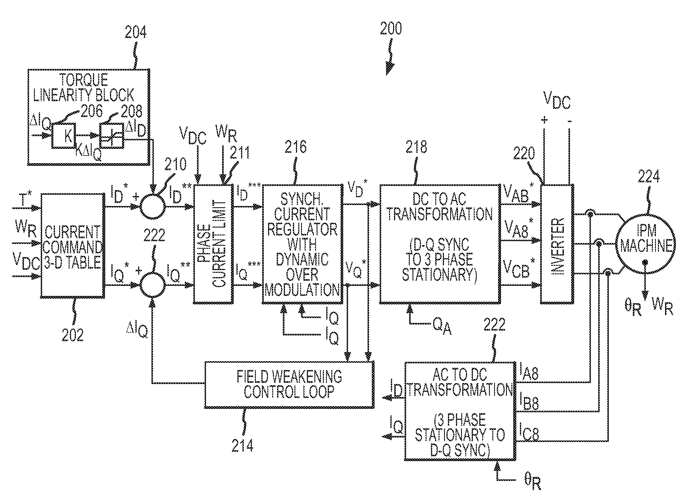
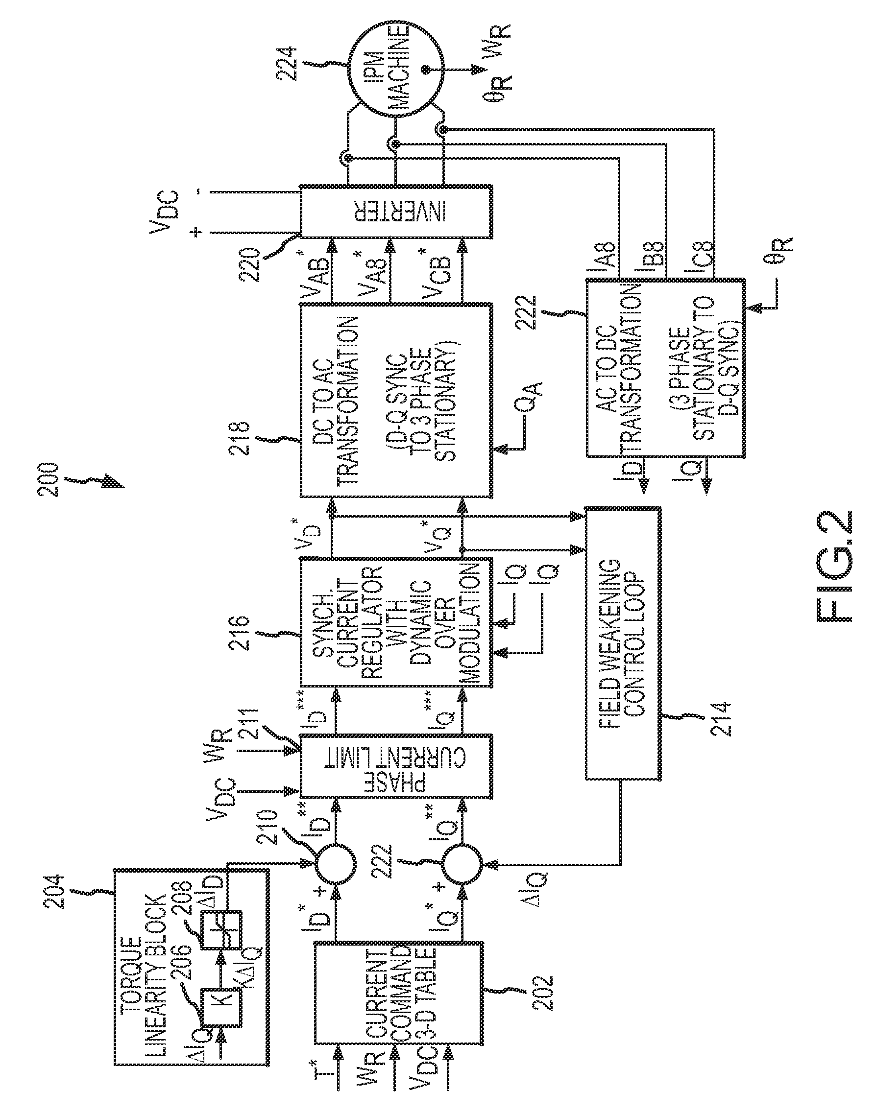
Systems and methods are disclosed to provide torque linearity in the field-weakening region for an IPM machine. The systems and methods adjust the q-axis and the d-axis components of the stator current commands of the IPM machine using a flux weakening and a torque linearity control loop respectively. Thereby, torque linearity is maintained during the field weakening region of operation of the IPM machine.

Description

TECHNICAL FIELD[0001]Embodiments of the present invention relate generally to electric machine control, and more particularly relate to techniques that affect torque linearity in a field weakening region of an electric machine.BACKGROUND[0002]An electric machine converts electrical power into mechanical force and motion. Electric machines are found in numerous applications including household appliances such as fans, refrigerators, and washing machines. Electric drives are also increasingly used in electric and hybrid-electric vehicles.[0003]A rotary electric machine generally has an internal rotating magnet, called the rotor, which revolves inside a stationary stator. The interaction between the rotor electromagnetic field with the field created by the stator winding creates the machine torque. The rotor may be a permanent magnet or it may be made of coils. However, if the rotor has permanent magnets embedded therein (i.e., the permanent magnets are not in the rotor surface), the e...

Claims


Application Information

Patent Timeline
Patent Type & Authority Patents(United States)
IPC IPC(8): H03K5/00
CPCB60L15/025H02P21/06H02P21/0089B60L2220/14B60L2200/26Y02T10/643Y02T10/64
Inventor GALLEGOS-LOPEZ, GABRIELSON, YO CHANPERISIC, MILUNHITI, SILVA
Owner GM GLOBAL TECH OPERATIONS LLC
Learn More