Hydraulic cylinder unit

Active Publication Date: 2010-07-27
WEBER HYDRAULIK GMBH
View PDF6 Cites 6 Cited by
  • Summary
  • Abstract
  • Description
  • Claims
  • Application Information

AI Technical Summary

Benefits of technology

[0009]The inventive principle thus utilizes the hydrodynamic effect of the hydraulic liquid in the converging gap in order to minimize the frictional forces between preferably the piston seal and the cylinder tube on the one hand and the rod seal and the piston rod on the other hand. Although the qualities of the running surface (roughness, material, surface treatment) are not the subject of the invention, it must be embodied such that, in combination with the running surface (inner surface of the cylinder tube or outer surface of the piston rod), with the seal it ensures optimum friction and wear behavior.
[0010]It has been found that the frictional force or damping properties of the hydraulic cylinder unit in accordance with the invention can be substantially reduced by using the piston seal and / or rod seal. Numerous possibilities and advantages result from this. Thus, the reduction in the size of the cylinder due to improved force utilization can lead to more numerous employment possibilities and to savings in costs. Furthermore, the improvement in the properties of suspension cylinders, due to reduced basic damping, leads to the fact that a greater portion is available for actively influencing system damping. In working cylinders, controllability and sensitivity can be markedly enhanced. In addition, new areas of application become available for the inventive cylinder units for cylinders that were previously not suitable due to inadequate effective force, frictional forces and thus interfering forces that were too high, or damping that was too high. Double-acting cylinders can also act as the hydraulic cylinder unit.
[0012]In accordance with the invention, the gap for the rod seal is embodied asymmetrical with respect to its center plane and open to the piston rod-side cylinder space so that at least in the outward-moving direction of the piston rod the hydrodynamic friction-reducing floating effect results.
[0013]If in addition an additional seal is arranged between the rod seal and the area of the cylinder unit and between it and the rod seal a recess acting as a reservoir for the hydraulic fluid that is carried out is arranged in the cylinder head, the extra hydraulic fluid carried out as a lubricating film can be collected there and the hydrodynamic friction-reducing floating effect can also be produced in the inward-moving direction of the piston rod.

Problems solved by technology

In addition, new areas of application become available for the inventive cylinder units for cylinders that were previously not suitable due to inadequate effective force, frictional forces and thus interfering forces that were too high, or damping that was too high.

Method used


Image

  • Hydraulic cylinder unit
  • Hydraulic cylinder unit
  • Hydraulic cylinder unit

Examples


Embodiment Construction

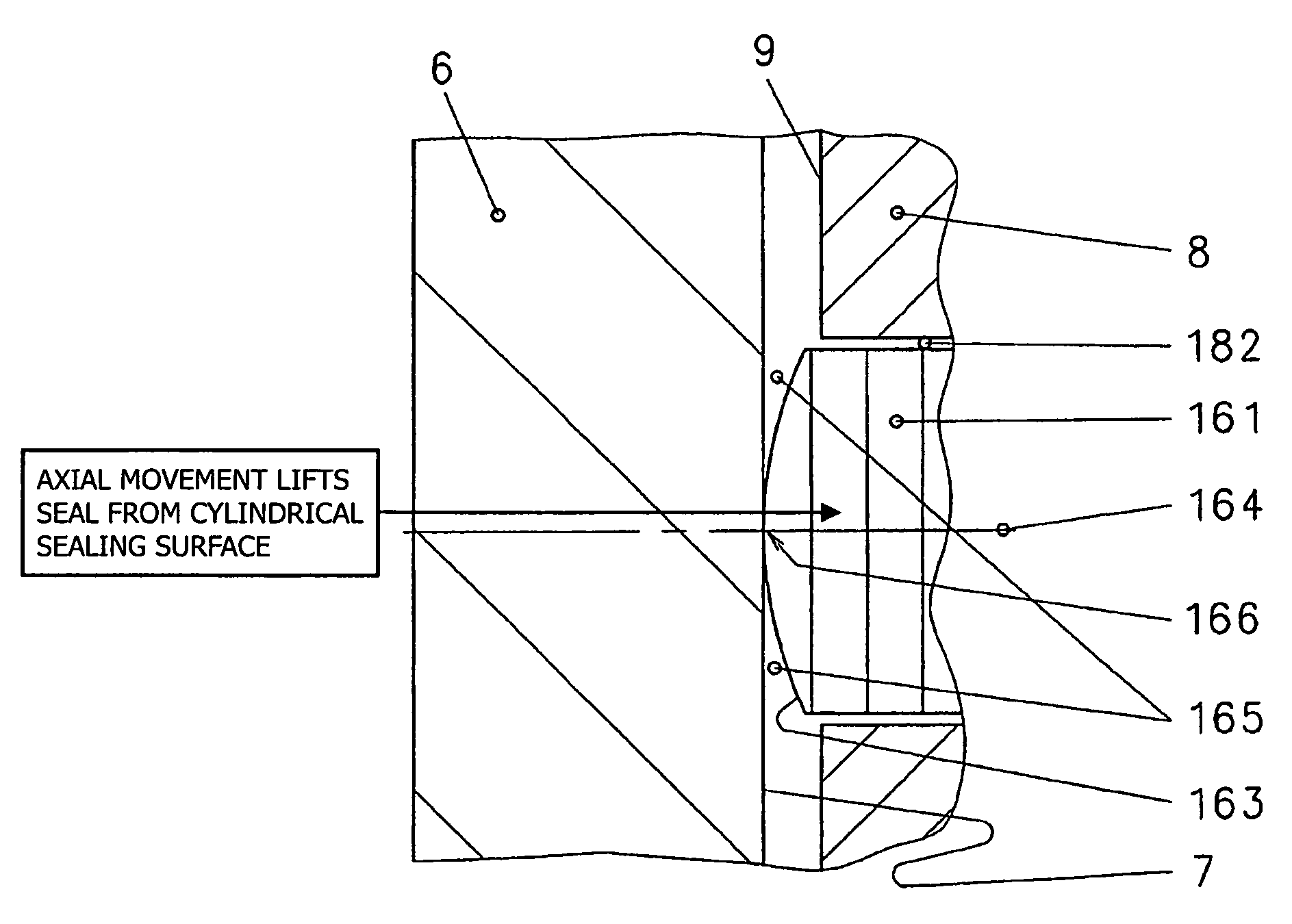
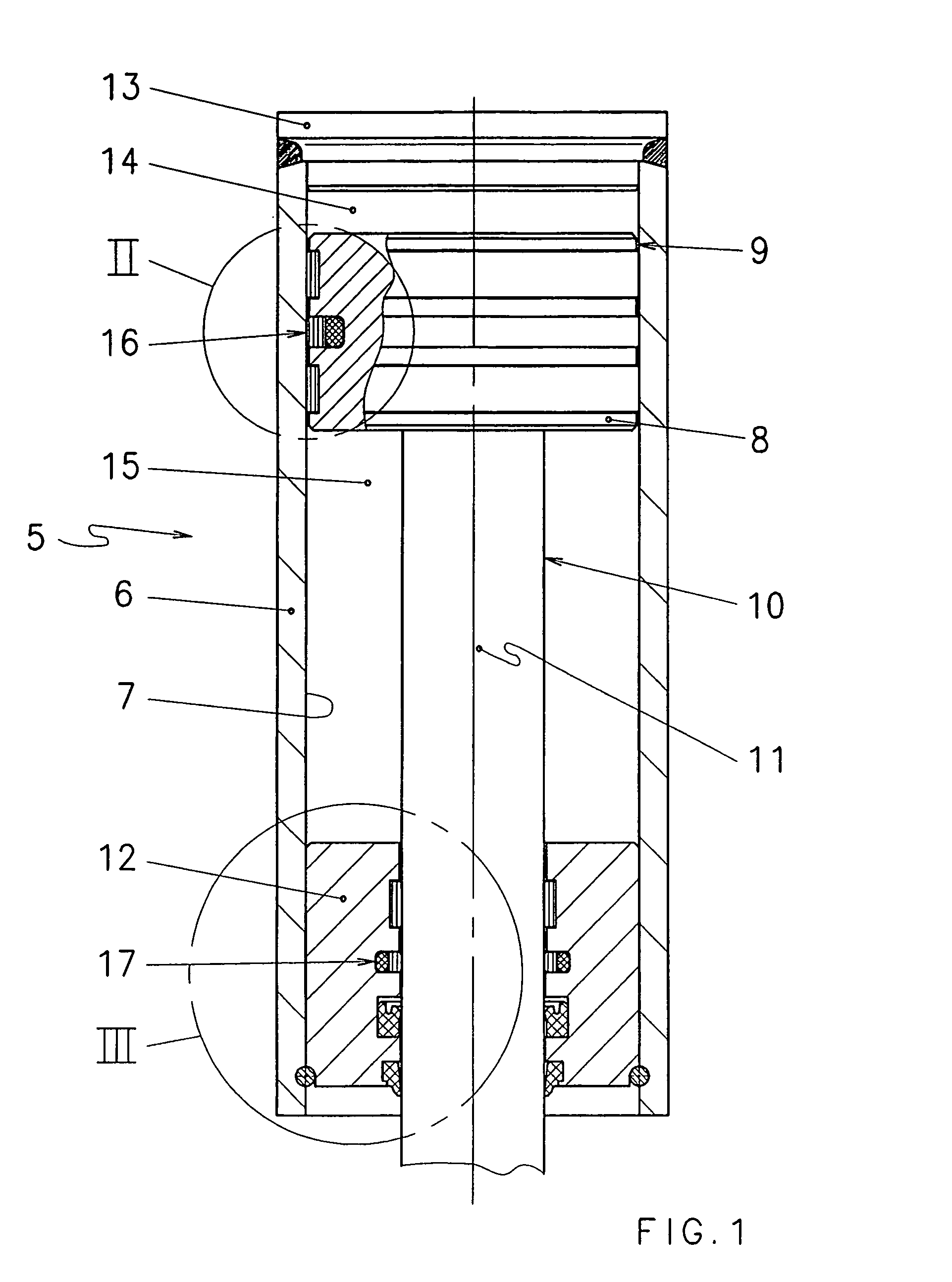
[0019]The cylinder unit illustrated in FIG. 1 and labeled 5 overall has a cylinder tube 6 on whose inner surface 7 a piston 8 having an outer surface 9 is guided. On the piston, a piston rod, labeled 10 overall, is joined to a rod surface 11 that extends out of the cylinder unit 5 via a cylinder head labeled 12 overall that is driven out when hydraulic fluid that is under pressure acts upon the cylinder space 14 that is formed between the piston 8 and the cylinder floor 13. If the cylinder unit 5 is embodied with double action, pressure can also act on the annular piston rod-side cylinder space 15 that is formed by the piston rod 10, the cylinder head 12, and the piston 8, driving the piston rod 10 in.

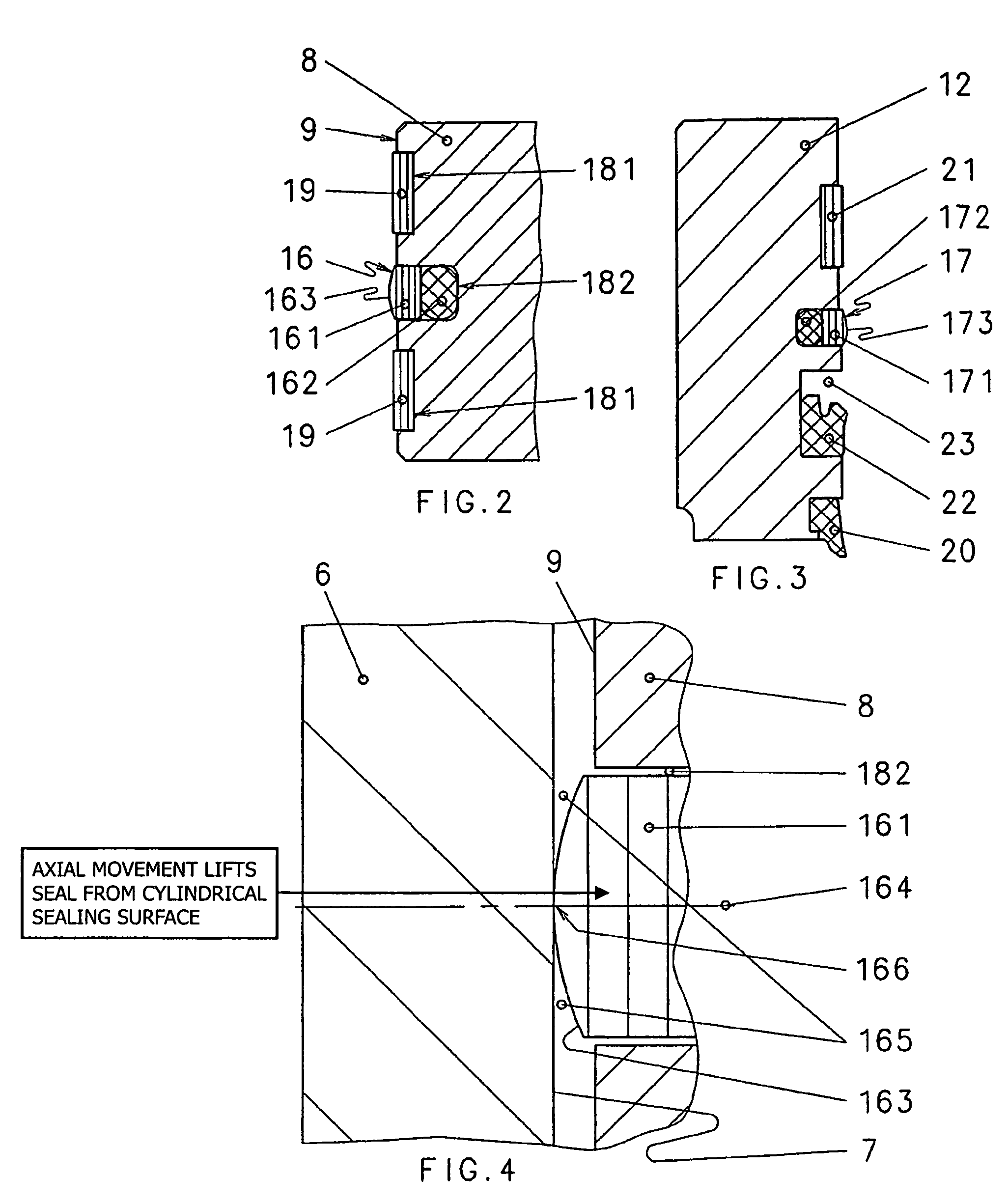
[0020]A piston seal labeled 16 overall is provided on the piston 8 between the cylinder space 14 and the piston rod-side cylinder space 15. Correspondingly, a rod seal labeled 17 overall is provided on the cylinder head 12 between the external area of the cylinder unit 5 and the piston...


PUM


Abstract

A hydraulic cylinder unit is provided with a rod seal and / or piston seal which has a surface that deviates from the vertical circular cylindrical surface of the piston head throughhole through which the piston rod passes or the vertical circular cylindrical surface of the cylinder interior while forming respective converging gaps with regard to the rod surface and the interior surface of the cylinder, respectively.

Description

BACKGROUND OF THE INVENTION[0001]The invention relates to a hydraulic cylinder unit, specifically a hydraulic cylinder unit with a cylinder tube having an inner surface with a piston that is guided thereon and that has an outer surface, with a piston rod joined thereto whose rod surface is guided on a cylinder head that closes the rod-side cylinder space, with at least one rod seal arranged therein that seals the piston rod-side cylinder space from the area of the cylinder unit between the rod surface and the cylinder head by means of a rotationally symmetrical inner seal surface, and with at least one piston seal arranged in the piston that seals the piston-rod side cylinder space and the cylinder space formed by the cylinder floor and the piston between the cylinder space inner surface and the outer surface of the piston by means of a rotationally symmetrical outer seal surface.[0002]Especially low-friction cylinder units are of interest for various purposes. Among these are cylin...

Claims


Application Information

Patent Timeline
Patent Type & Authority Patents(United States)
IPC IPC(8): F16J15/24F16J9/06
CPCF15B15/1461F15B15/1452
Inventor FISCHER, MARCUS
Owner WEBER HYDRAULIK GMBH
Why Eureka
Try Eureka